Configuration and Installation
3
XB-DMX512 DMX512 Interface
Configuration and Installation
Setting the Device DIP Switch
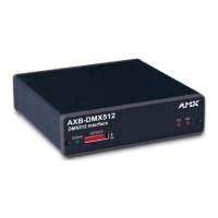
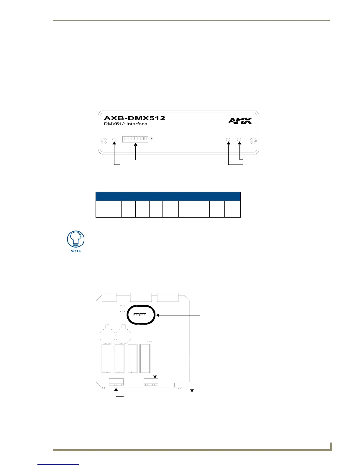
The 8-position DEVICE DIP switch on the front panel (FIG. 1) sets the AXlink identification number for
the AXB-DMX512. Make sure the device number matches the number assigned in the Axcess software
program.
The following table describes the values on the
DEVICE DIP switch.
Terminating the Device
When using the DMX input and if this device is the last device in a chain of DMX512 devices, you must
terminate the line. To terminate the device, position jumpers on jumper pin trios JP4 and JP5 (FIG. 2):
FIG. 1 AXB-DMX512 (front view)
Device DIP Switch Settings
Position 12345678
Value 1 2 4 8 16 32 64 128
AXlink
DEVICE
ON
RXTX
Device ID DIP Switch
Axlink activity LED
DMX512 (Transmit) LED
DMX512 (Receive) LED
The DIP Switch located to the right of the DEVICE DIP switch is not used - no
settings are required, and any setting will work.
FIG. 2 Location of termination jumpers pins (JP1-JP5) and lithium batteries
COR
JP5
JP4
front
Termination Jumpers
(JP4 / JP5)
DEVICE DIP Switch
The DIP Switch located to the
right of the DEVICE DIP switch
is not used - no settings are
required, and any setting
will work.
 Loading...