Configuration and Installation
5
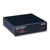
XB-DMX512 DMX512 Interface
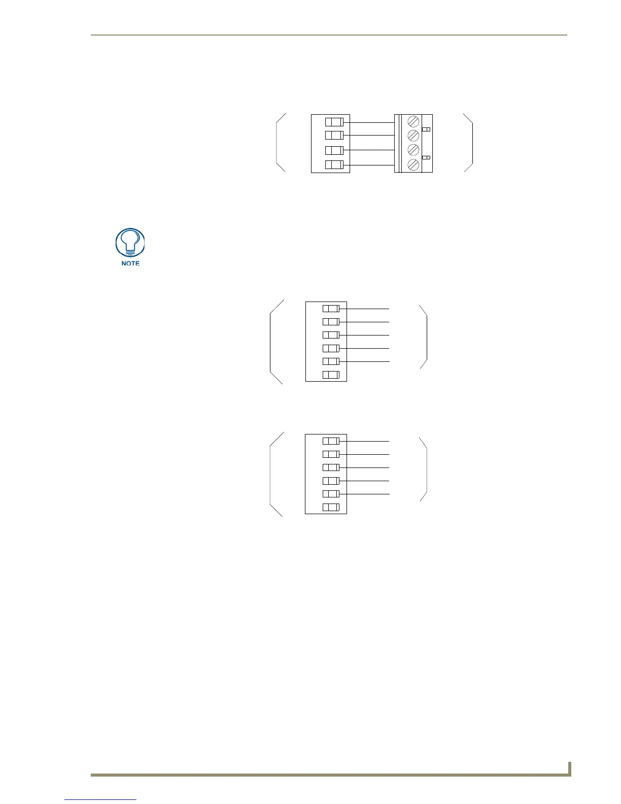
Using AXlink communication
Connect the AXlink wiring to the connector on the AXB-DMX512, as shown in FIG. 5.
Using IN and OUT DMX512 data communication
1.
For transmit wiring, connect the DMX512 wiring to the OUT connector, as shown in FIG. 6.
2. For receive wiring, connect the DMX512 wiring to the IN connector, as shown in FIG. 7.
Mounting the AXB-DMX512 in a Rack
To mount the AXB-DMX512 in an equipment rack, you will need an AC-RK rack mounting kit.
1. Remove the two screws on the front panel of the AXB-DMX512.
2. Remove the front panel and the space bracket behind the panel.
3. Remove the rubber feet on the bottom of the unit, if necessary. Insert a scissors blade or other sharp
object into the side of one of the rubber feet and pull it off. Do the same to remove the other three
rubber feet.
4. Place the unit in the appropriate opening in the AC-RK.
5. Place the front panel of the AXB-DMX512 on the front of the rack over the unit and secure the
screws.
FIG. 5 AXlink wiring
PWR
AXP
AXM
GND
PWR
AXP
AXM
GND
Device
AXlink connector
on AXB-DMX512
Some DMX devices only use DATA+ and DATA-. Connect these to DATA1+ and
DATA1-, leaving DATA2+ and DATA- unconnected.
The DATA2 In and Out ports are not Currently supported.
FIG. 6 DMX512 transmit wiring
FIG. 7 DMX512 receive wiring
DMX 512 OUT
connector on AXB-DMX512
GND
DATA1-
DATA1+
DATA2-
DATA2+
NC
GND
DATA1-
DATA1+
DATA2-
DATA2+
Device
DMX 512 IN
connector on AXB-DMX512
GND
DATA1-
DATA1+
DATA2-
DATA2+
NC
GND
DATA1-
DATA1+
DATA2-
DATA2+
Device
 Loading...