OSCILLATION SPEED CONTROL ADJUSTMENT
Page 10
The speed of oscillation can be adjusted using test mode or under
actual operating conditions.
Speed Adjustment Using Test Mode
To obtain an accurate speed setting, the test (garden) hose pres-
sure must be the same as the expected header pressure.
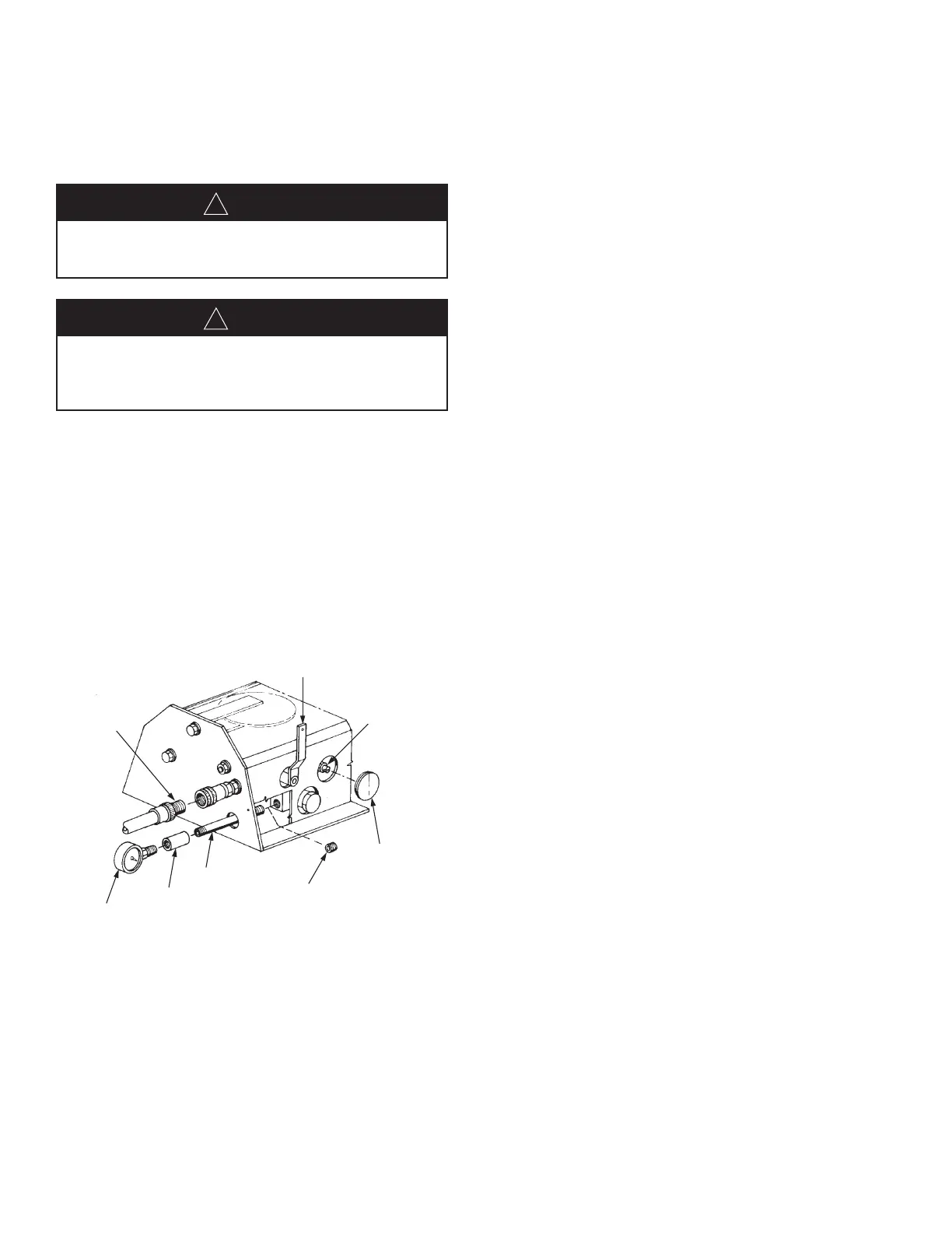
1. To verify hose pressure, install pressure gauge by completing
the following steps. (Refer to Figure 7.)
a. Using a 1/4 in. allen wrench, remove 1/4 in. pipe plug
through access hole below garden hose connection.
b. Screw a 1/4 in. nipple (5 in. long) in place of the pipe plug
so that nipple protrudes through access hole.
c. Screw coupling onto pipe nipple.
d. Screw pressure gauge into pipe coupling.
FIGURE 7
006012
2. Remove plug from speed adjustment access hole located on
right side of enclosure.
3. Connect a garden hose (3/4-11 1/2 NH) to fitting at back of
oscillating mechanism enclosure.
4. Turn selector valve handle (at side of enclosure) up to
T
EST/MANUAL position.
5. Turn on water supply to garden hose.
6. As monitor is oscillating, adjust speed by turning control screw
c
lockwise to decrease speed or counterclockwise to increase
speed.
7. Turn off water supply to garden hose.
8. Return selector valve handle to RUN position (pointed to back
of enclosure). Secure handle with visual inspection seal.
9. If used, remove pressure gauge, coupling, and nipple.
Reinstall pipe plug.
Speed Adjustment Under Operating Condition
1. Remove plug from speed adjustment access hole located on
right side of enclosure. (See Figure 7.)
2. Turn on main water supply to monitor.
3. As monitor is oscillating, adjust speed by turning control screw
(clockwise to decrease speed or counterclockwise to increase
speed).
4. Turn off main water supply.
5. Clean filter element as indicated in Step 2 on Page 9.
WARNING
!
FORCE OF DISCHARGE STREAM CAN CAUSE SEVERE
PERSONAL INJURY. DO NOT OPERATE MONITOR WHEN
PERSONNEL ARE IN PATH OF STREAM.
WARNING
!
OSCILLATING MECHANISM CONTAINS MOVING PARTS
THAT CAN CAUSE SEVERE PERSONAL INJURY. DO NOT
OPERATE MONITOR WITH COVER REMOVED FROM
ENCLOSURE.
REMOVE PLUG
TO INSTALL
GAUGE
SPEED
ADJUSTMENT
SCREW
NIPPLE
COUPLING
PRESSURE
GAUGE
CONNECT
GARDEN
HOSE
PLACE SELECTOR VALVE IN
“TEST/MANUAL” POSITION
REMOVE HOLE
PLUG TO ACCESS
ADJUSTMENT
SCREW
 Loading...