FOR MODELS: JGW, JGR AND JGJ SECTION 5 - MAINTENANCE
1/01 PAGE 5 - 9
7. Before removing the crankshaft from the crankcase, wooden saddles or a
notched wooden crate with sides high enough to prevent the webs or oil slinger
from touching bottom should be prepared in order to store the crankshaft during
maintenance - even though it may be out for only a short time. In addition, the
crankshaft should be adequately protected from above so that dropped tools or
equipment cannot mar the surface of pins and journals.
8. Turn the crankshaft so that sling lifting point(s) are above the center of gravity of
the shaft, so that it does not want to rotate when lifted. Lift straight up with the
ends of the crankshaft parallel to the frame. Two persons will be needed to
safely remove the crankshaft as well as a crane or lift due to the weight of the
crankshaft (see Table 5-1). Appropriately sized nylon slings should be used dur-
ing this operation to avoid marring of the running surface of the crankshaft.
Great care must be taken during this operation since the shaft could bind and
become damaged.
NOTE: THE LOWER HALF BEARING SHELLS SOMETIMES HAVE A TENDENCY TO
STICK TO THE SHAFT JOURNALS BECAUSE OF THE CLOSE FITTING OILY
SURFACES OF THE TWO PARTS. THEREFORE, WHEN THE SHAFT HAS
BEEN LIFTED CLEAR OF THE SADDLES, APPROXIMATELY 1/4 inches OR 6
mm, CHECK TO MAKE SURE THAT THE LOWER HALF BEARING SHELLS
HAVE NOT COME OUT WITH THE SHAFT. IF SO, THE BEARING SHELLS
SHOULD BE TAPPED BACK ONTO THE SADDLES BEFORE LIFTING THE
SHAFT ANY FURTHER.
9. While one person operates the crane, raising it very slowly, the second person
must grasp the crankshaft at the drive end with one hand on the counterweight
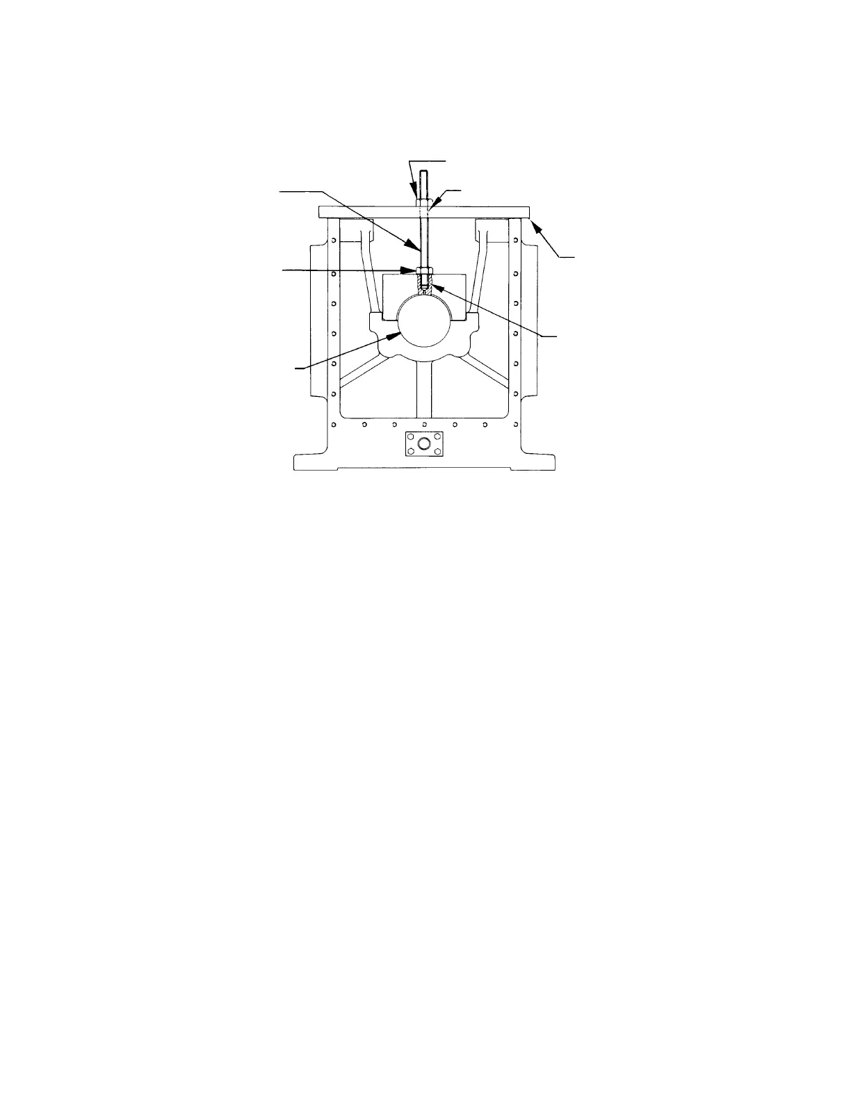
FIGURE 5-5: BEARING CAP PULLER
16” (406 mm) Long
Steel Bar
5/8-11 UNC (Jack Nut) Turn this Nut
to Jack Bearing Cap straight up.
7” (178 mm) Long
5/8-11 UNC
Threaded Rod
5/8-11 UNC
Lock Nut
Crankshaft
5/8-11 UNC
Puller Hole
Drill an 11/16” (17.5 mm) Hole
 Loading...