FOR MODELS: JGW, JGR AND JGJ SECTION 4 - LUBRICATION AND VENTING
PAGE 4 - 14 1/01
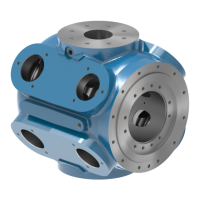
Description
Divider valves are comprised of three to eight valve blocks fastened to a segmented base-
plate. O-rings are used to seal between the valve blocks and the baseplate and between the
baseplate segments. These divider valves are used in a single line, progressive lubrication
system and can be used for dispensing oil or grease. Valves and baseplate segments are
normally supplied with Buna-N O-rings.
Check valves are installed at the inlets of all lube points.
Valve blocks containing metering pistons discharge a predetermined amount of lubricant
with each cycle. Valve blocks can be single or twin and can be externally singled or cross-
ported. Outlets not to be used when singling or crossporting must be plugged.
A by-pass block can be used in any position on the baseplate. The use of a by-pass block
allows the addition or deletion of lubrication points without disturbing existing tubing. Both
outlets under a by-pass block must be plugged.
The valve blocks and by-pass blocks are fastened to a baseplate mounted on the machine
to be lubricated. The baseplate contains the divider valve's inlet and outlet connections,
interrelated passageways and built-in check valves. All piping of lubricant to and from the
divider valve is connected to the baseplate.
The baseplate consists of one inlet block, three to eight intermediate blocks, one end block
and three tie rods. Gasket plate seals are included with the baseplate segments. The valve
block capacity of each baseplate is dependent upon the number of intermediate blocks in
the baseplate. There must be a minimum of three working valves on each valve and base-
plate assembly.
Standard Electronic-Lubricator Digital No-Flow Timer Switch - DNFT
The DNFT is a microprocessor-based switch used to sense no-flow or slow-flow conditions
in the compressor cylinder lubrication system to facilitate alarm and/or shutdown. The DNFT
also contains an amber light-emitting diode (LED) cycle indicator to provide a positive visual
indication of system operation. The Ariel DNFT includes a proximity switch. The standard
DNFT is factory set for (3) three minutes from no-flow to alarm/shutdown signal and is not
adjustable. Optional programmable models are available. Introduced in September of 1996,
the DNFT replaced the traditional mechanical no-flow switch and is standard on all new
units. Since its introduction, the DNFT has undergone a series of design enhancements and
several versions are in service. The current DNFT is shown in Figure 4-4:
The DNFT works thru a magnetic pin which cycles back and forth as the divider valve piston
moves, flashing the amber LED and indicating a complete cycle of the divider valve. The
DNFT operates on a non-replaceable sealed internal lithium battery, with an expected bat-
tery life of 6 to 10 years depending on cycle time. Optional models are available with a fac-
tory replaceable battery. Battery failure results in a fail safe DNFT no-flow output signal for
shutdown. Battery failure requires replacement of the DNFT. Expired DNFT’s may be
returned for partial credit.
While earlier versions of the DNFT required position adjustment on the magnet housing
assembly, DNFT’s supplied after August 1997 no longer require such adjustment. To
replace the DNFT, remove conduit and mark wiring connections. Remove wiring and the old
 Loading...