FOR MODELS: JGW, JGR AND JGJ SECTION 5 - MAINTENANCE
1/01 PAGE 5 - 5
6. Reinstall the spacer bars. All spacer bars are match-marked for proper location.
They must be reinstalled in their original location. Tighten all spacer bar bolts to
the value listed in Table 1-11 on page 1-15.
7. Examine the removed top cover and side cover gaskets. If there is any doubt
about their condition, install new gaskets. Before installing old or new gaskets,
apply an anti-seize lubricant to both sides to aid in their easy removal at a later
date. Replace the top cover and crosshead guide cover. Tighten all capscrews.
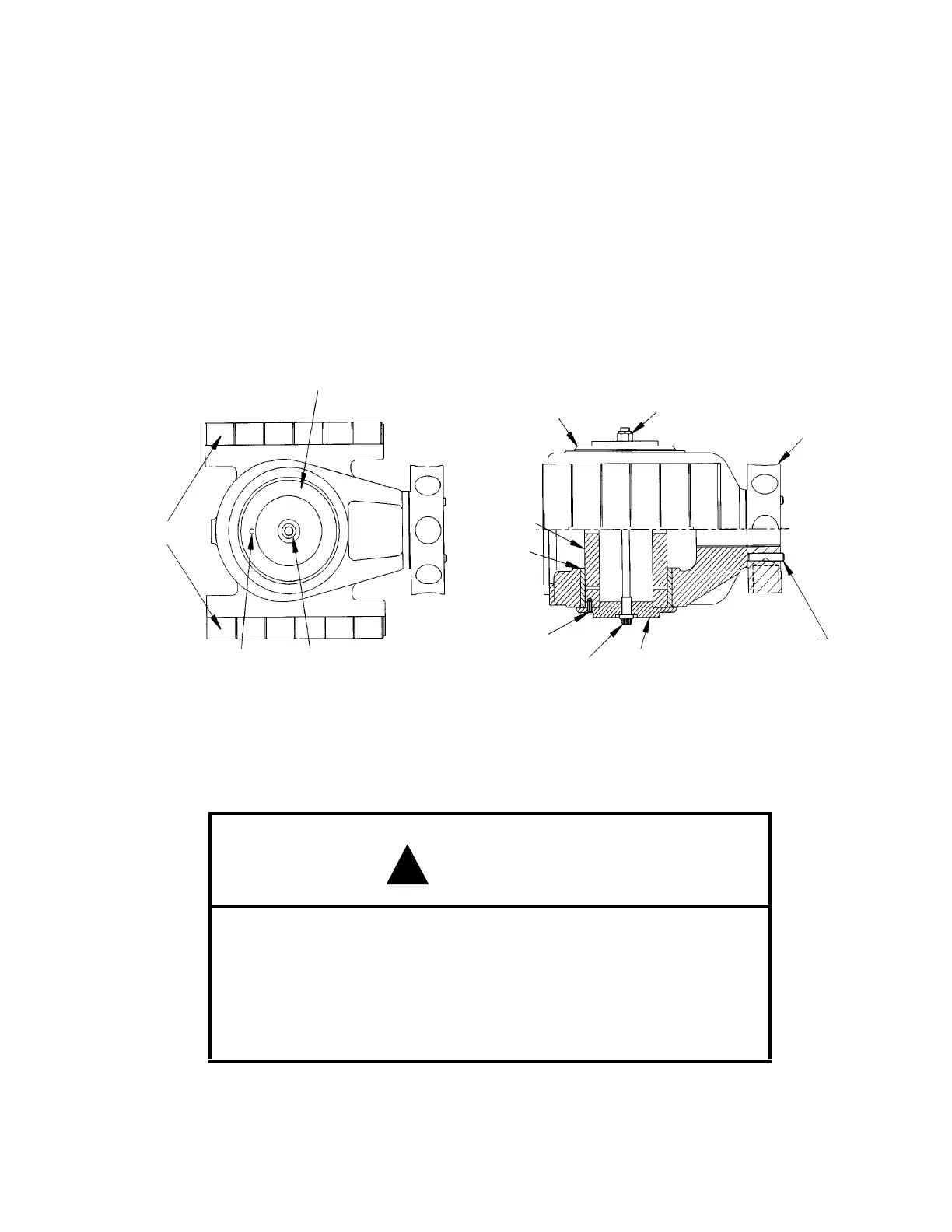
Crosshead - Removal
FIGURE 5-2: CROSSHEAD - TYPICAL
CAUTION
BEFORE REMOVING THE CYLINDER HEAD, BACK OFF ALL
CAPSCREWS TO 1/8 INCHES (3 mm). MAKE SURE THAT THE
HEAD IS LOOSE AND THE CYLINDER IS VENTED. SEE
IMPORTANT SAFETY INFORMATION PLATES ON UNIT TOP
COVER, (REFERENCE FIGURE 1-3: ON PAGE 1-4 FOR LOCA-
TION.)
End Plate
Thru Bolt
Lock Nut
Crosshead Nut
Set Screw - Loosen
Before Turning Nut
End Plate
Thru Bolt
Roll Pin
Shoes
Thru BoltRoll Pin
End Plate
Crosshead
Pin
Bushing
!
 Loading...