7. USB 2.0 ports 1 and 2. These two 4-pin Universal Serial Bus (USB) ports connect to
USB 2.0 devices.
8. USB 2.0 ports 3 and 4. These two 4-pin Universal Serial Bus (USB) ports connect to
USB 2.0 devices.
9. Video Graphics Adapter (VGA) port. This 15-pin port is for a VGA monitor or other
VGA-compatible devices.
10. COM port. This 9-pin COM1 port is for pointing devices or other serial devices.
11. PS/2 Keyboard port (purple). This port is for a PS/2 keyboard.
• We recommend that you connect a high-denition front panel audio module to this
connector to avail of the motherboard high-denition audio capability.
• If you want to connect a high denition front panel audio module to this connector, set
the Front Panel Select item in the BIOS to [HD Audio]. See section 2.4.3 Chipset for
details.
• The front panel audio I/O module is purchased separately.
1.10.2 Internal connectors
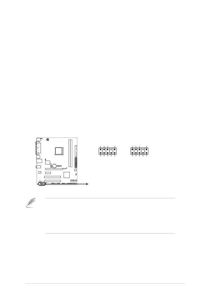
1. Front panel audio connector (10-1 pin AAFP)
This connector is for a chassis-mounted front panel audio I/O module that supports
either High Denition Audio or AC`97 audio standard. Connect one end of the front
panel audio I/O module cable to this connector.
M4N68T-M
M4N68T-M Analog front panel connector
AAFP
PIN 1
GND
PRESENCE#
SENSE1_RETUR
SENSE2_RETUR
PORT1 L
PORT1 R
PORT2 R
SENSE_SEND
PORT2 L
HD-audio-compliant
pin definition
PIN 1
AGND
NC
NC
NC
MIC2
MICPWR
Line out_R
NC
Line out_L
Legacy AC’97
compliant definition
ASUS M4N68T-M 1-21
 Loading...