12 ASUS P5A User’s Manual
III. INSTALLATION
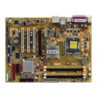
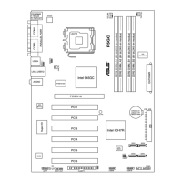
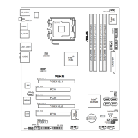
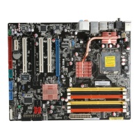
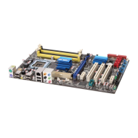
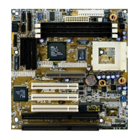
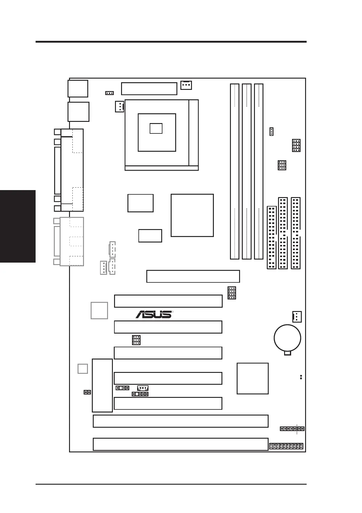
ASUS P5A Motherboard Layout
Motherboard Layout
III. INST ALLATION
R
(OPTIONAL)
SGNT
SREQ
SOLOID
ALi
Aladdin V
M1541
AGPset
ALi M1543C
Chipset
(IDE
Controller)
CR2032
3 Volt
Lithium Cell
DIMM Socket 1 (64-bit, 168-pin module)
01
DIMM Socket 2 (64-bit, 168-pin module)
23 45
Floppy Drives
Secondary IDE
Primary IDE
DIMM Socket 3 (64-bit, 168-pin module)
PS2
KBMS
KBPWR
Top: Mouse
Bottom: Keyboard
Top: USB 1
Bottom: USB 2
USB
Board Power Input
for ATX Power Supply
CPU ZIF Socket 7
CPU Thermal Sensor
(Hardware Monitor)
Audio
Chipset
COM 1
COM 2
Line
Out
Parallel Port
Line
In
Mic
In
AGP Slot
Modem
Connector
PCI Slot 3
PCI Slot 4
PCI Slot 5
Programmable
BIOS EEPROM
ISA Slot 1
ISA Slot 2
Panel Connections
PCI Slot 2
PCI Slot 1
512KB/1MB
Pipelined Burst
L2 Cache
Tag RAM
Game/Midi Port
CD1
AUX
BUS Frequency
FS0
FS1
FS2
FS3
CPU Voltage
VID0
VID1
VID2
VID3
Frequency Ratio
BF2
BF1
BF0
CHA_FAN
Wake-on-LAN Connector
PWR_FAN
Hardware
Monitor
Chassis Int.
Alarm Lead
CLRTC
IDELED
IR
+
Row
CPU_FAN
VIO1
TRPWR
SMBus Connector
Dimmed components are optional.
 Loading...