EasyManuals Logo

Asus P5GC-MX GBL User Manual

Asus P5GC-MX GBL
96 pages
To Next Page IconTo Next Page
To Previous Page IconTo Previous Page
Page #40 background imageLoading...
Page #40 background image
1-28 Chapter 1: Product introduction
2. IDE connectors (40-1 pin PRI_IDE)
The onboard IDE connectors are for Ultra DMA 100/66/33 signal cables.
There are three connectors on each Ultra DMA 100/66/33 signal cable:
blue, black, and gray. Connect the blue connector to the motherboard’s IDE
connector, then select one of the following modes to congure your device(s).
Pin 20 on the IDE connector is removed to match the covered hole on the
Ultra DMA cable connector. This prevents incorrect insertion when you
connect the IDE cable.
Use the 80-conductor IDE cable for Ultra DMA 100/66/33 IDE devices.
If any device jumper is set as “Cable-Select,” make sure all other device
jumpers have the same setting.
R
P5GC-MX/GBL
P5GC-MX/GBL
IDE Connector
PRI_IDE
Drive jumper setting Mode of device(s) Cable connector
Single device Cable-Select or Master - Black
Two devices Cable-Select Master
Slave
Black
Gray
Master
Slave
Master
Slave
Black or gray

Table of Contents

Questions and Answers:

Question and Answer IconNeed help?

Do you have a question about the Asus P5GC-MX GBL and is the answer not in the manual?
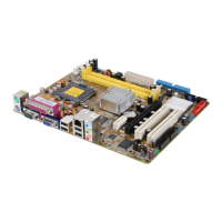
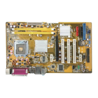
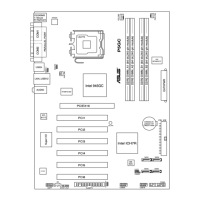
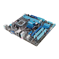
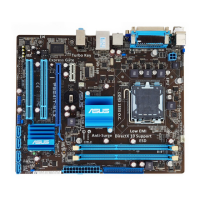
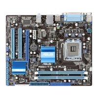
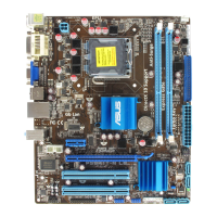
Asus P5GC-MX GBL Specifications

General IconGeneral
Form FactorMicro ATX
ChipsetIntel 945GC
CPU Socket TypeLGA 775
Memory TypeDDR2
Memory StandardDDR2 667/533
Maximum Memory4GB
Integrated GraphicsIntel GMA 950
LAN ChipsetRealtek RTL8111B
LAN Speed10/100/1000Mbps
CPU SupportIntel Core 2 Duo, Pentium D, Pentium 4, Celeron
Memory Slots2
Storage Interface4 x SATA 3Gb/s
Back Panel Ports1 x PS/2 Keyboard, 1 x PS/2 Mouse, 1 x Parallel, 1 x COM, 4 x USB 2.0, 1 x LAN (RJ45), 3 x Audio Jacks
USB Ports8 x USB 2.0
Audio Channels6 Channels

Related product manuals