1-24 Chapter 1: Product introduction
1.10.2 Internal connectors
1. Front panel audio connector (10-1 pin AAFP)
This connector is for a chassis-mounted front panel audio I/O module that supports
either High Denition Audio or AC`97 audio standard. Connect one end of the front
panel audio I/O module cable to this connector.
P8H67-V
P8H67-V Front panel audio connector
AAFP
PIN 1 PIN 1
SENSE2_RETUR
SENSE1_RETUR
PRESENCE#
GND
PORT2 L
SENSE_SEND
PORT2 R
PORT1 R
PORT1 L
HD-audio-compliant
pin definition
NC
NC
NC
AGND
Line out_L
NC
Line out_R
MICPWR
MIC2
Legacy AC’97
compliant definition
If you want to connect a high-denition front panel audio module to this connector, ensure
that the Front Panel Type item in the BIOS is set to [HD Audio]. If you want to connect an
AC97 front panel audio module to this connector, set the item to [AC97]. See section 2.5.6
Onboard Devices Conguration for details.
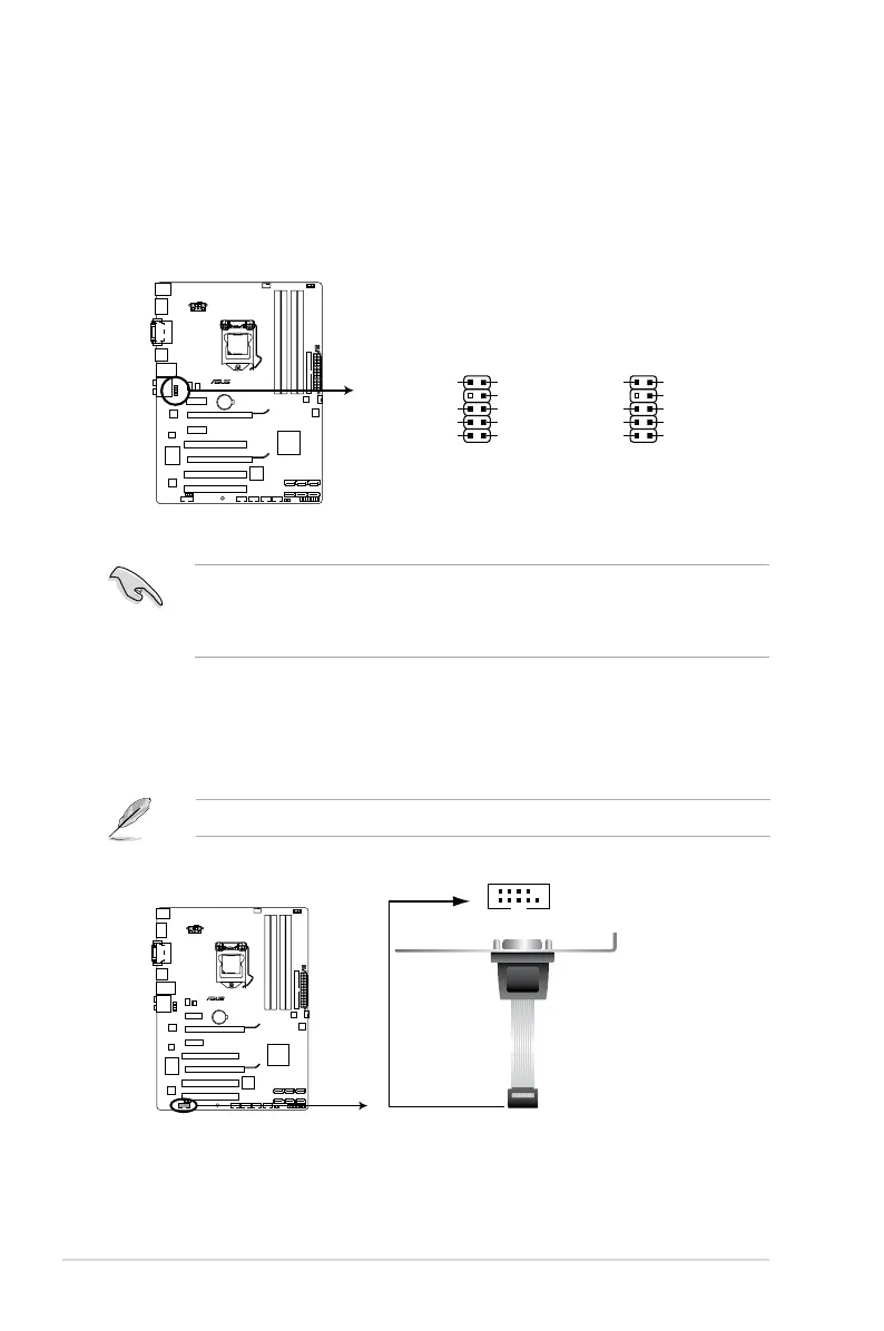
2. Serial port connectors (10-1 pin COM1)
The connector is for a serial (COM) port. Connect the serial port module cable to the
connector, then install the module to a slot opening at the back of the system chassis.
The serial port bracket (COM1) is purchased separately.
P8H67-V
P8H67-V Serial port (COM1) connector
PIN 1
COM1
 Loading...