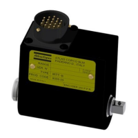
IRTT-B User Guide
4 (8) 9836 4436 01 Revision 2010-01
GENERAL
The IRTT-B transducer provides torque measurement on a rotary
transducer, with optional angle reading.
The torque measurement is performed with a precise extensometer
bridge with special brushes to transfer the signal from the rotating
shaft to the housing; these brushes have been developed to be very
reliable and should not have the need of any maintenance through
out its life.
The angle reading is performed with a rotating magnetic sensor
providing 1024 pulses per revolution.
A built in memory stores identification and calibration data for
automatic reading from the measurement instrument.
TECHNICAL
• Torque Measurement Range: 1 ÷ 5000 Nm
• Angle (optional): 1024 pulses per turn
• Static accuracy: ± 0.25% of rated max. transducer capacity
• Overload capacity: 125% of rated max. transducer capacity
• Temperature stability: 0.1% of capacity / °C
• Bridge resistance: 350 ohm
• Operation humidity: 10-75% non condensing
• Operating temperature: 5 to 40°C
The transducer comes with Atlas Copco BLM calibration
certificate.
The calibration data is marked on the transducer label (when
installing the item always use this data, not the nominal values)
CONNECTOR PIN OUT
TRANSDUCER BUILT IN MEMORY
The built in memory consist in a eeprom, which stores the
following data:
• Identification
• Calibration (Nm)
• Full scale value (% of cal. Value)
• Sensitivity (2mV/V)
• Pulses / rev
• Serial Number.
• Date of latest calibration
• Next Calibration date
• Source of Calibration
TORQUE ONLY MODELS
Model Capacity (Nm) Drive Ordering No.
5-I06 5
¼” hex
8059 0942 05
20-I06 20
¼” hex
8059 0942 10
20-06 20
¼” square
8059 0942 15
25-10 25
3/8” square
8059 0942 20
75-10 75
3/8” square
8059 0942 25
180-13 180
1/2” square
8059 0942 30
500-20 500
¾” square
8059 0942 35
750-25 750
1” square
8059 0942 40
1400-25 1400
1” square
8059 0942 45
3000-38 3000
1 ½” square
8059 0942 52
5000-38 5000
1 ½” square
8059 0942 56
TORQUE AND ANGLE MODELS
Model Capacity (Nm) Drive Ordering No.
1A-I06 1 ¼” hex 8059 0943 96
2A-I06 2 ¼” hex 8059 0943 01
5A-I06 5 ¼” hex 8059 0943 06
5A-06 5 ¼” square 8059 0943 08
20A-I06 20 ¼” hex 8059 0943 11
20A-06 20 ¼” square 8059 0943 16
25A-10 25 3/8” square 8059 0943 21
75A-10 75 3/8” square 8059 0943 26
180A-13 180 1/2” square 8059 0943 31
500A-20 500 ¾” square 8059 0943 36
750A-25 750 1” square 8059 0943 41
1400A-25 1400 1” square 8059 0943 46
3000A-38 3000
1 ½” square
8059 0943 52
5000A-38 5000
1 ½” square
8059 0943 56
OPERATIONS
Select the correct transducer having a torque capacity not less than
the maximum torque capacity of the tool used. Secure the tool
output spindle to the transducer input socket (hexagon shaft). Fit
the correct socket to the transducer output square drive (or bit in
bit-holder) and make sure it is secured.
Connect the transducer to the measuring instrument with the proper
cable. If you use an ACTA instrument the calibration data will be
loaded automatically and no manual entering of the value is
required.
If you use another measuring instrument the transducer shunt
calibration value and the angle pulses must be entered manually.
The shunt calibration value is marked on the transducer, the bridge
impedance is 350 Ohm and a 43,575 Ohm resistor is necessary.
Make sure to align the tool/transducer, to avoid any influence from
side forces which may affect the measurement.
If a tool is tested with a reaction bar the effective radial position of
the reaction bar point should not be less than a certain value (see
the next table and figure); not observing this requirement and to
exceed the maximum torque rating may cause a permanent damage
to the transducer.
Pin Function
A Excitation +
B Excitation –
C Signal +
D Signal –
E –
F Angle encoder cw trail (for versions with angle)
G Eeprom Clock
H Angle encoder cw lead (for versions with angle)
J Eeprom data
K-L-
M-N
–
P Ground (angle and eeprom)
R + 5V for angle reading (for versions with angle)
S –
T + 8/12V eeprom power supply
U-V –

 Loading...