8
Drilling in wet holes
The infl ow of water into the drill hole is expected when drilling water
wells, but can also occur when drilling deep holes for other purposes.
Water infl ow does not normally create problems for drilling, although
both “too little” and “too much” can be troublesome.
Too little water tends to bind the drill cuttings into a paste, which sticks
to the drill pipes or the hole wall and can easily form collars or plugs.
The problem can be lessened by adding water to the fl ushing air, thus
increasing the fl uidity of the cuttings. Fluidity can be further improved
by adding washing detergent to the water.
N.B.
Remember to increase the lubrication dosage when injecting
water into the fl ushing air!
If the infl ow of water is so great that it restricts the bailing of cuttings
and water from the hole, then extra fl ushing will be needed. See Extra
fl ushing, page 7.
Water injection
Water injection is normally used to suppress dust when drilling dry
holes. COP down-the-hole hammers are designed to function with a
certain amount of water injection. As an example, only 2—6 litres of
water per minute (at 18 bar air pressure), injected into the main air line,
is suffi cient to control the dust when drilling with the COP 64. Too much
water injection will have a very negative infl uence on the penetration
rate of the hammer.
Rule of thumb: 0.25 l water per m
3
com pressed air consumed by
the hammer during the drilling sequence.
CAUTION
The injection point for water and foaming concentrate should always be
located after the main shut-off valve on the rig. If not, there is a danger
of the mixture being pumped back through the main air line and into the
compressor. This could seriously damage the compressor.
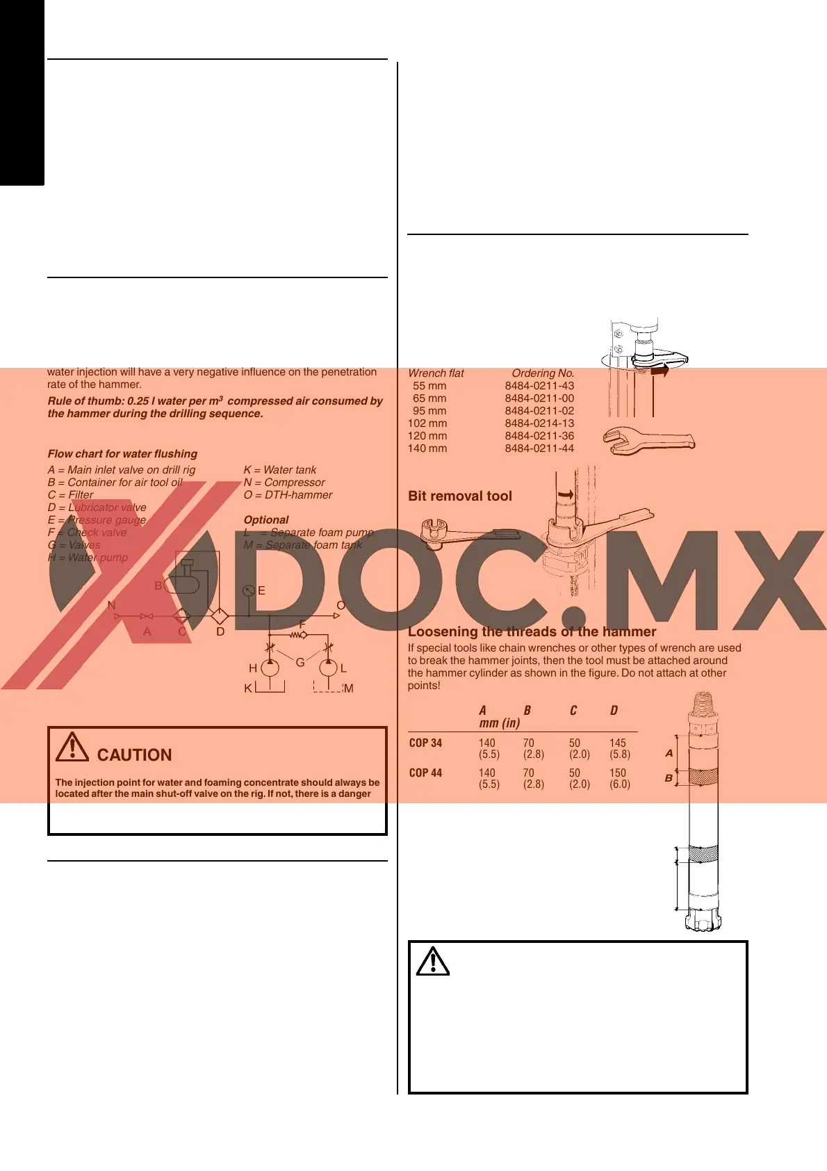
Flow chart for water fl ushing
A = Main inlet valve on drill rig K = Water tank
B = Container for air tool oil N = Compressor
C = Filter O = DTH-hammer
D = Lubricator valve
E = Pressure gauge Optional
F = Check valve L
= Separate foam pump
G = Valves M = Separate foam tank
H = Water pump
Foam injection
Foam can be used in DTH drilling to improve the fl ushing performance
(especially in non-consolidated formations). It does this by “lifting up”
the cuttings out of the hole, and also has the desir able effect of sealing
the hole walls. Foaming concentrate is pumped into the compressed-
air line in the form of a concentrate/water mixture. Atlas Copco foam-
ing concentrate has lubricating properties and contains corrosion
inhibitors, which prevent seizing in the hammer.
N.B.
Before using foaming concentrates not supplied by Atlas Copco,
please consult your Atlas Copco representative for advice.
With Atlas Copco foaming concentrate, a mixture of 0.5–2 per cent
concentrate/water is normally recommended. When drilling in water-
bearing rock and other diffi cult formations, it might be necessary to
increase the percentage of concentrate, and also to add polymers to
the operating air. This will help to stabilize the hole walls and increase
the lifting capacity of the foam. The concentrate/water mixture is
injected into the main air line by means of a high-pressure pump.
Minimum requirements for the water-injection pump are as follows:
min. pressure = 30 bar
min. fl ow = 20 l/min.
After drilling with foam, it is recommended that residual foam should
be fl ushed out of the hammer to prevent corrosion. This is done by
injecting water only into the air, and so fl ushing the foam out the
hammer. Oil should then be poured into the drillstring and the hammer
operated for a few minutes before the drill string is withdrawn from the
hole. If the hammer is then to be stored for a long time, it should be
dismantled and all parts cleaned and oiled thoroughly.
Tools
Tools for removing the drill bit and top sub
from the DTH hammer
The threaded connections of the driver-chuck and top sub can become
very tightly tensioned during drilling. There are special tools for remov-
ing the bit and top sub from the cylinder of the DTH hammer, and these
should be used whenever possible.
DANGER
Take great care when breaking the driver-chuck joint using the bit
removal tool in combination with reverse rotation. If the shaft of the tool
is not locked or touching the edge of the feed beam, the shaft can turn
with great force when breaking the driver chuck joint.
Keep your hands and clothing well clear of the hammer/drill string
when it is rotated. Entanglement can result in serious injury.
Blows against hammer or bit can cause fragments of metal to fl y.
Always wear goggles when breaking joints.
Wrench for pipe-jointing
and top sub
Wrench fl at Ordering No.
55 mm 8484-0211-43
65 mm 8484-0211-00
95 mm 8484-0211-02
102 mm 8484-0214-13
120 mm 8484-0211-36
140 mm 8484-0211-44
Bit removal tool
C
B
A
D
A B C D
mm (in)
COP 34 140 70 50 145
(5.5) (2.8) (2.0) (5.8)
COP 44 140 70 50 150
(5.5) (2.8) (2.0) (6.0)
COP 54 180 70 50 175
(7.0) (2.8) (2.0) (6.9)
COP 64.2/64.3 190 80 60 175
(7.5) (3.1) (2.4) (6.9)
COP 84.2L 190 80 60 240
(7.5) (3.1) (2.4) (9.4)
COP 84 200 80 80 250
(8.0) (3.1) (3.1) (10.0)
Loosening the threads of the hammer
If special tools like chain wrenches or other types of wrench are used
to break the hammer joints, then the tool must be attached around
the hammer cylinder as shown in the fi gure. Do not attach at other
points!
ENGLISH
 Loading...