- 23 -
DESCRIPTION
Generator function:
Turn switch S6 to position 1. The solenoid valve
Y2G via the speed regulator SR controls the motor
and allows it to reach maximum speed (the normal
control system is switched off). Lamp H1 is
activated (sockets X1.1, X1.2, X1.3 are under
tension).
The generator can be switched off by turning
switch S6 to position 0.
In the case of an insulation fault, lamp H2 of the
system is activated. When the red lamp H2 is active,
a reset can only be made by stopping and restarting
the unit.
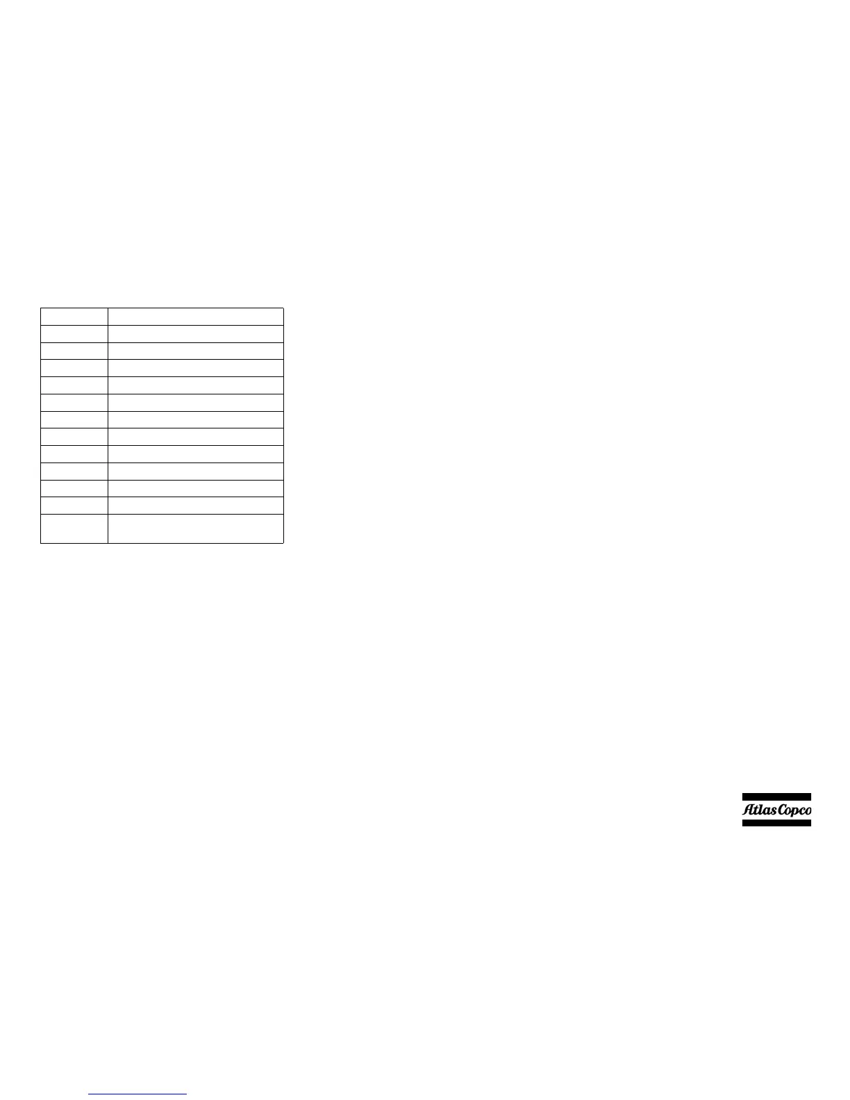
Reference Name
D1 Diode
G3 Generator
H3 Lamp (Power control)
K5 Contactor 4-pole
K6 Insulation Monitoring Relay
Q1 Main circuit breaker 4-pole
S6 Thermal contact (N/O)
S7 Switch (Generator-compressor)
X1.1 Socket outlet
X1.2 Socket outlet
X1.3 Socket outlet
Y2 Solenoid valve (Generator
operation)
 Loading...