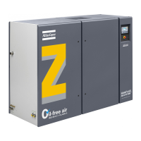
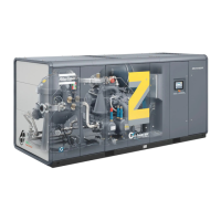
Instruction book
2920 1472 03 31
4. The inlet grids and ventilation fan should be installed in such a way that any recirculation of
cooling air to the compressor is avoided. The air velocity to the grids should be limited to 5
m/s. The required ventilation capacity (per compressor installed) to limit the compressor room
temperature can be calculated as follows:
Qv = 1.16 N / dT for ZT15 up to ZT22
Qv = (1.16 N + 3.2) / dT for ZT15 up to ZT22 Full-Feature
Qv = 1.09 N / dT for ZT30 up to ZT45
Qv = (1.09 N + 5.5) / dT for ZT30 up to ZT45 Full-Feature
Qv = 0.21 N / dT for ZR30 up to ZR45
Qv = (0.21 N + 5.5) / dT for ZR30 up to ZR45 Full-Feature
Qv = required ventilation capacity in m³/s
N = shaft input of the compressor in kW
dT = temperature rise over ambient
If cooling air ducts are installed, the maximum allowable pressure drop over the ducts is 30
Pa. Common ducting for several compressors is not allowed.
5. Lay out the drain piping from automatic condensate outlets towards the condensate collector.
The drain pipes must not dip into the water of the collector. It is recommended to provide a
funnel to allow visual inspection of the condensate flow.
6. Elektronikon control system with control panel.
7. See section 2.3 for the recommended cable size of the supply cables. Check that the
electrical connections correspond to the local codes. The installation must be earthed and
protected against short circuits by fuses in all phases. An isolating switch must be installed
near the compressor.
8. Provide a condensate drain valve in the lowest part of the pipe between the compressor outlet
valve and the air net.
9. On ZT: optional main switch.
9. On ZR30 up to ZR45: position of cooling water pipes. Remove the plastic plugs (if provided)
from the compressor water pipes and connect the pipes to the cooling water circuit. Provide a
valve in the compressor water inlet pipe and outlet pipe.

 Loading...


