6
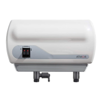
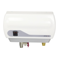
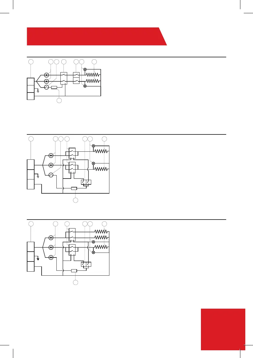
Electrical Diagram
1. Terminal block
2. Thermal cut-out with reset
3. Thermal cut-out
4. Relay
5. Switch 0- Off
1- Low
2- Medium
3- High
6. Light
7. Heating element
8. Read sensor
1. Terminal block
2. Thermal cut-out with reset
3. Thermal Cut out
4. Relay
5. Switch 0- Off
1- Low
2- Medium
3- High
6. Light
7. Heating element
8. Read sensor
1. Terminal block
2. Thermal cut-out with reset
4. Relay
5. Switch 0- Off
1- Low
2- Medium
3- High
6. Light
7. Heating element
8. Read sensor
8.5kW-10.5kW (240V)
13kW (240V)
3.0 (110V), 3.8 -6.5Kw (240V) - Install Line 1 (L1), E(G)-Ground, Line 2 (L2)
L1/L2 = Line1/Line2 (Black or Red)
E(G) = Ground (Green/Yellow)
*N = Neutral (White or Silver)
*Neutral acts as Line 2 (L2) for 220V/240V
1 2
8
3 4 5 6 7
R.R
85
º
Led 1
Led 2
85
º
57
º
L1
G
L2
2
3 4 6 7
1 5
8
R.R
85
º
Led 1
Relay
Switch
Relay
Led 2
85
º
57
º
L1
G
L2
2
4 6 7
1 5
8
R.R
85
º
Led 2
Relay
Switch
Relay
Led 1
85
º
85
º
L1
G
L2

 Loading...