ZoneLogix™ PRO Zone Controller User Guide | Revision 1.0 November 2019 | Page 20
3
Basic Mode System Operation & Configuration
3.1
System Start Up – Apply 24 VDC Power
3.1.1 Zone Discovery
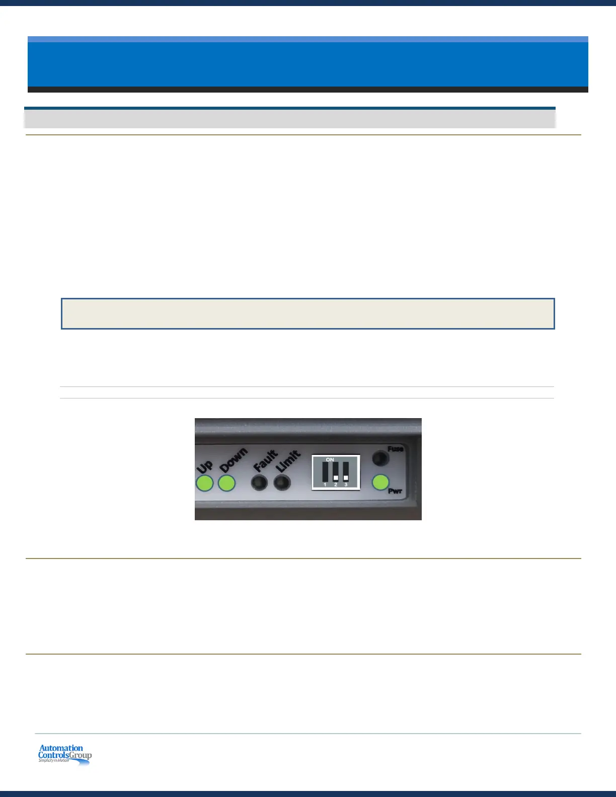
When powered on, the Master Zone Controller initiates a Branch discovery process. The Master communicates
sequentially to upstream Zone Controllers and initializes each zone. Each zone should have the following LEDs
illuminated:
• The Pwr LED should be illuminated solid
• The EOB Zone Controller should have the Down comm LED illuminated solid
• The Master Zone Controller should have the Up comm LED illuminated and the Down comm LED will blink
at a ½ second rate only when the optional Branch Monitor is connected.
• All Standard Zone Controllers should have the Up and Down comm LEDs illuminated solid
NOTE: When illuminated, the Up comm LED indicates a good connection to the zone on the left. The Down comm LED indicates a
good connection to the zone on the right.
• Check all photoeye sensors to ensure the indicator LEDs are illuminated correctly (see manufacturer’s manual)
Figure 10: Standard Zone Controller LEDs in Normal Operation
3.1.2 Lost Package Detection
During power up, beginning at the exit end and then flowing zone-by-zone after very brief intervals to avoid creating
high inrush current at the power supply, each zone then runs for up to the value of the Sleep Timer (default is 5
seconds) or until an object arrives at the respective zone sensor, whichever comes first. This process will ‘find’ objects
that may have been stranded between zone sensors if power was removed while an object was being transported.
3.1.3 Sleep Timer
A zone will run for up to the value of Sleep Timer (default is 5 seconds) until either an object arrives at the zone sensor,
or until the timeout expires. The purpose of this functionality is to ensure that an object is not stranded between
sensors.
 Loading...