A-47
(A)
Photo
electric
sensor
(B)
Fiber
optic
sensor
(C)
Door/Area
sensor
(D)
Proximity
sensor
(E)
Pressure
sensor
(F)
Rotary
encoder
(G)
Connector/
Socket
(H)
Temp.
controller
(I)
SSR/
Power
controller
(J)
Counter
(K)
Timer
(L)
Panel
meter
(M)
Tacho/
Speed/ Pulse
meter
(N)
Display
unit
(O)
Sensor
controller
(P)
Switching
mode power
supply
(Q)
Stepper
motor&
Driver&Controller
(R)
Graphic/
Logic
panel
(S)
Field
network
device
(T)
Software
(U)
Other
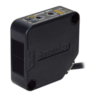
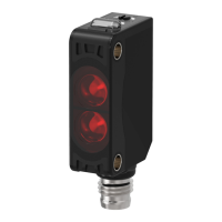
Amplier Built-in type with Universal voltage
Photoelectric sensor circuit Connection
Diffuse reflective type
● BEN300-DFR ● BEN300-DDT
● DC voltage(NPN/PNP synchronous output) ● Free power(Relay contact output)
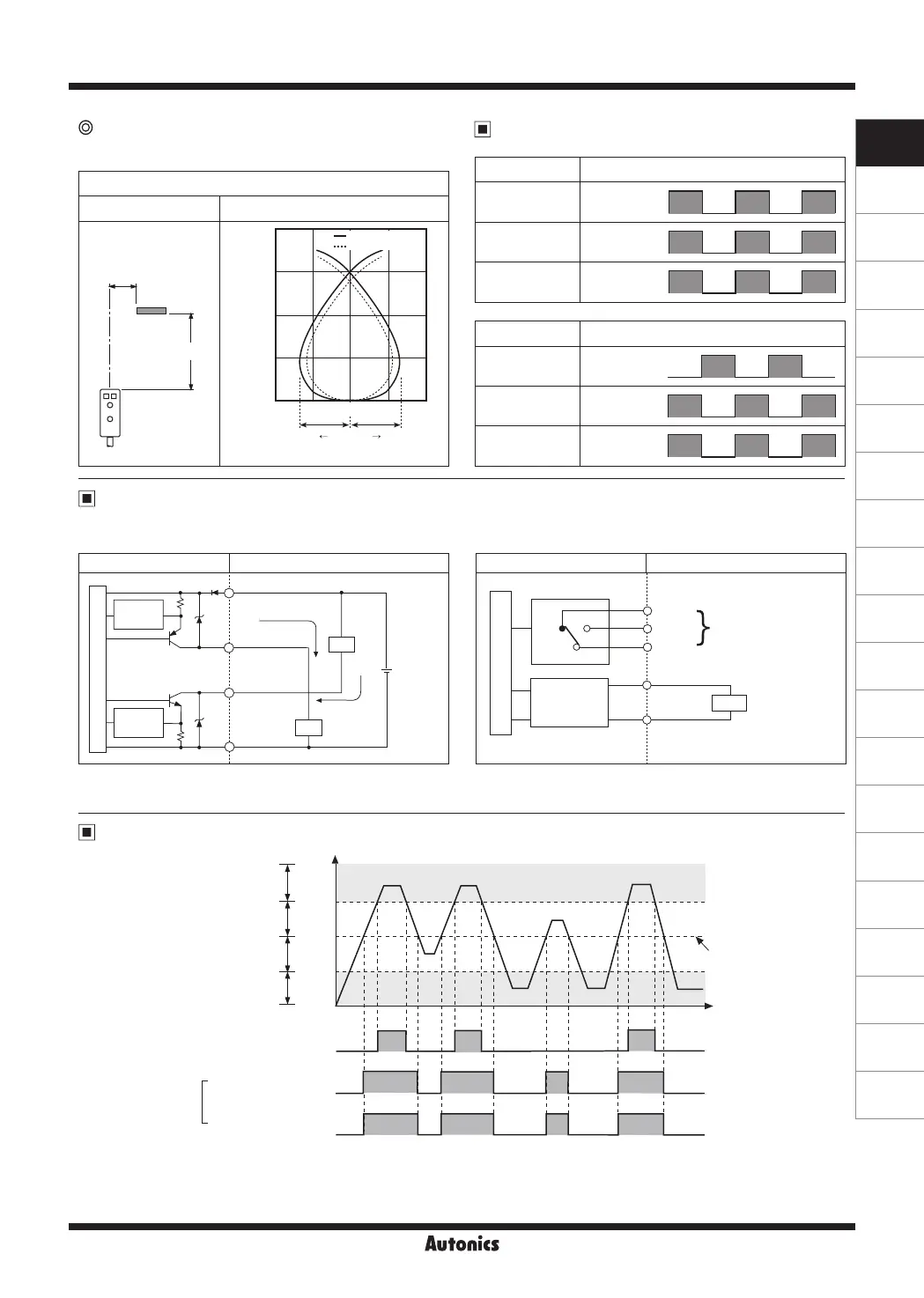
Sensing area characteristic
Measuring method Data
Sensing area(mm)
Standard sensing target:
Non-glossy white paper
100×100mm
Diffuse reective
ℓ
1
L
ℓ
1
ℓ
1
800
600
400
200
0
10 5 0 -5 -10
Left RightCenter
Sensing distance L(mm)
Operation level
Stable operation level
Operation mode
Operation mode Light ON
Receiver operation
Received light
Interrupted light
Operation indicator
(red LED)
ON
OFF
Transistor output
ON
OFF
Operation mode Dark ON
Receiver operation
Received light
Interrupted light
Operation indicator
(red LED)
ON
OFF
Transistor output
ON
OFF
※
In case of product with the output protection device, if terminals of control output are short circuited or overcurrent
condition exists, the control output turns OFF due to protection circuit.
Control output diagram
Photoelectric sensor circuit Connection
(Brown)+V
(Blue)0V
(White)
PNP output
(Black)
NPN output
Max. 200mA
Max. 200mA
Load
Load
Overcurrent
protection
Overcurrent
protection
Main circuit
12-24VDC
±10%
+
-
24-240VAC±10%
24-240VDC±10%
Power
Relay
Free power
circuit
(Gray)Tb
(Black)Ta
(White)Tc
Contact output(1c)
(Blue)
(Brown)
Main circuit
+
-
Operation timing diagram
※
The waveforms of “Operation indicator” and “Transistor output” are for Light ON operation.
They are opposite operation for Dark ON operation.
Unstable operation area
Stable light OFF area
Transistor output
(Relay)
Light ON
operation
ON
OFF
ON
OFF
ON
OFF
Stable light ON area
Stability Indicator
(green LED)
Operation level
Operation indicator
(red LED)
High
Incident
light
level
Low
 Loading...