B-34
BF4 Series
※
Connect Diode at external terminal for inductive load.
BF4R / BF4G BF4RP / BF4GP
Fiber optic sensor circuit Connection Fiber optic sensor circuit Connection
(blue) 0V
12-24VDC
12-24VDC
+
-
+
-
(brown) +V
(black)
Control output
(white)
Self-diagnosis output
Max. 50mA
Max. 100mA
※
※
Load
Load
Load
Load
(blue) 0V
(brown) +V
(black) Control output
(white)
Self-diagnosis
output
Max. 50mA
Max. 100mA
※
※
Main circuit
Main circuit
BF4R-E / BF4G-E BF4R-R / BF4G-R
Fiber optic sensor circuit
Connection
Fiber optic sensor circuit
Connection
12-24VDC 12-24VDC
+
-
+
-
(white)
Self-diagnosis output
(white)
Self- diagnosis output
(brown) +V
(brown) +V
(pink)
(pink)
(orange)
(orange)
※
Load
Load
Load
※
Load
(black)
Control output
(black) Control output
Max. 50mA
(blue) 0V
(blue) 0V
External
synchronization input
ON input of remote
sensitivity setting
Emission
disable input
OFF input of remote
sensitivity setting
Max.
100mA
※
※
Max. 50mA
Max. 100mA
Main circuit
Main circuit
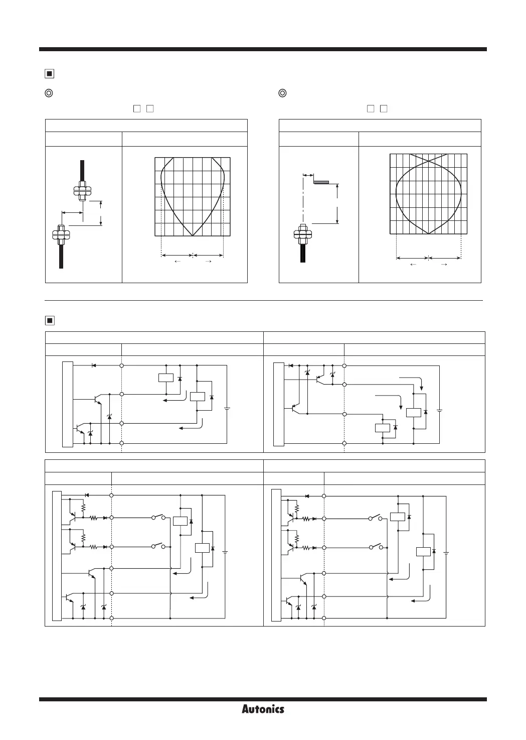
Control Output Diagram
Feature Data
● Measurement: BF4 (- )+ FT-420-10 ● Measurement: BF4 (- ) + FD-620-10
Through-beam type Diffuse reflective type
Parallel shifting characteristic
Measuring method Data
L
ℓ
1
Receiver
Emitter
0
400
100
200
300
500
600
200 100
-100 -200
0
Left
Center Right
ℓ
1
ℓ
1
Sensing distance L (mm)
Sensing area
ℓ
1
(mm)
Sensing area characteristic
Measuring method Data
L
ℓ
1
0
30
60
90
120
150
180
0
-10 -30
1030
-20
20
Left
Center Right
ℓ
1
ℓ
1
Sensing distance L (mm)
Sensing area
ℓ
1
(mm)
 Loading...