B-39
Fiber Optic Amplier
(A)
Photoelectric
Sensors
(B)
Fiber
Optic
Sensors
(C)
Door/Area
Sensors
(D)
Proximity
Sensors
(E)
Pressure
Sensors
(F)
Rotary
Encoders
(G)
Connectors/
Connector Cables/
Sensor Distribution
Boxes/ Sockets
(H)
Temperature
Controllers
(I)
SSRs / Power
Controllers
(J)
Counters
(K)
Timers
(L)
Panel
Meters
(M)
Tacho /
Speed / Pulse
Meters
(N)
Display
Units
(O)
Sensor
Controllers
(P)
Switching
Mode Power
Supplies
(Q)
Stepper Motors
& Drivers
& Controllers
(R)
Graphic/
Logic
Panels
(S)
Field
Network
Devices
(T)
Software
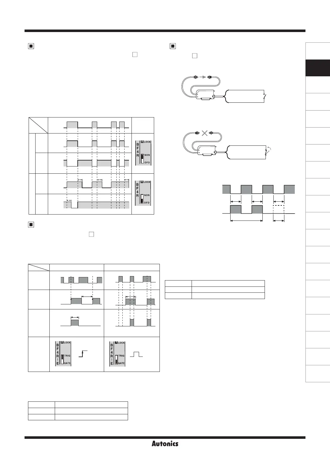
Standard type and External input sensitivity setting type
both contain the built-in OFF Delay timer, approx. 40ms.
The timer works when the timer selection switch is set to
[OFD]
.
The output turns off after remaining for additional 40ms at
OFF position of the sensing output. It is useful when the
response time of the connected device is slow or when the
sensing signal from a tiny object is too short.
External Synchronization Input
Function
[BF4R -E]
By using external synchronization function, the time
for making sensing can be specified by external
synchronization. (trigger synchronization and gate
synchronization)
State Signal condition
High 4.5-30VDC or Open
Low 0-1VDC
State Signal condition
High 4.5-30VDC or Open
Low 0-1VDC
Timer (OFF Delay) Function
[BF4R/BF4G/BF4RP/BF4GP/BF4 -R]
Stop Transmission Function
[BF4 -E]
-Operation Test
This function is available under light ON state only and it is
for checking normal state of the sensor.
<Input signal condition for External synchronization>
<Input signal condition for Stop transmission>
※
1: Right before transfer detection signal of the sensor as
control output.
※
T≥0.5ms (using interference prevention function: T≥0.7ms)
※
①
: Transmission area,
②
: Stop transmission area
※
1: If transmission is stopped, control output must turn
on, but if control output does not turn on, it seems that
sensor has some problems.
※
T≥0
.5ms
(when using interference prevention function T≥0.7ms)
[If input of stop transmission is at High or Open state,
light is transmitted.]
[If input of stop transmission is at Low, light is transmitted.]
High
(OFF)
Low
(ON)
Input of stop
transmission
Sensing output
(If it is in ON
state when light
is not received)
T T T
① ① ①①
② ② ②
Normal
Abnormal
※
1
ON
OFF
※
Control output is fixed
as 40ms.
Trigger synchronization Gate synchronization
Sensing
signal
※
1
External
synchroni-
zation
input
Control
output
External
synchroni-
zation
selection
switch
Approx. 40ms
High
Low
High
Low
ON
OFF
ON
OFF
ON
OFF
ON
OFF
T T
: GATE
: TRIG
Timer
selection
switch
Light
ON
Dark
ON
Light
ON
Dark
ON
ON
OFF
ON
OFF
ON
OFF
ON
OFF
T T T
T
Sensing
Non-
Sensing
<Time Chart>
T
≒
40
㎳
Sensing
state
Output
operation
Normal
Timer
(orange) Input of stop transmission
(blue) 0V
High or
Open
(orange) Input of stop transmission
(blue) 0V
Low
 Loading...