B-23
(A)
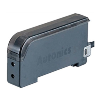
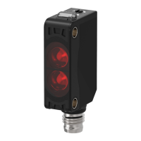
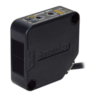
Photo
electric
sensor
(B)
Fiber
optic
sensor
(C)
Door/Area
sensor
(D)
Proximity
sensor
(E)
Pressure
sensor
(F)
Rotary
encoder
(G)
Connector/
Socket
(H)
Temp.
controller
(I)
SSR/
Power
controller
(J)
Counter
(K)
Timer
(L)
Panel
meter
(M)
Tacho/
Speed/ Pulse
meter
(N)
Display
unit
(O)
Sensor
controller
(P)
Switching
power
supply
(Q)
Stepping
motor&
Driver&Controller
(R)
Graphic/
Logic
panel
(S)
Field
network
device
(T)
Software
(U)
Other
Fiber Optic Amplier
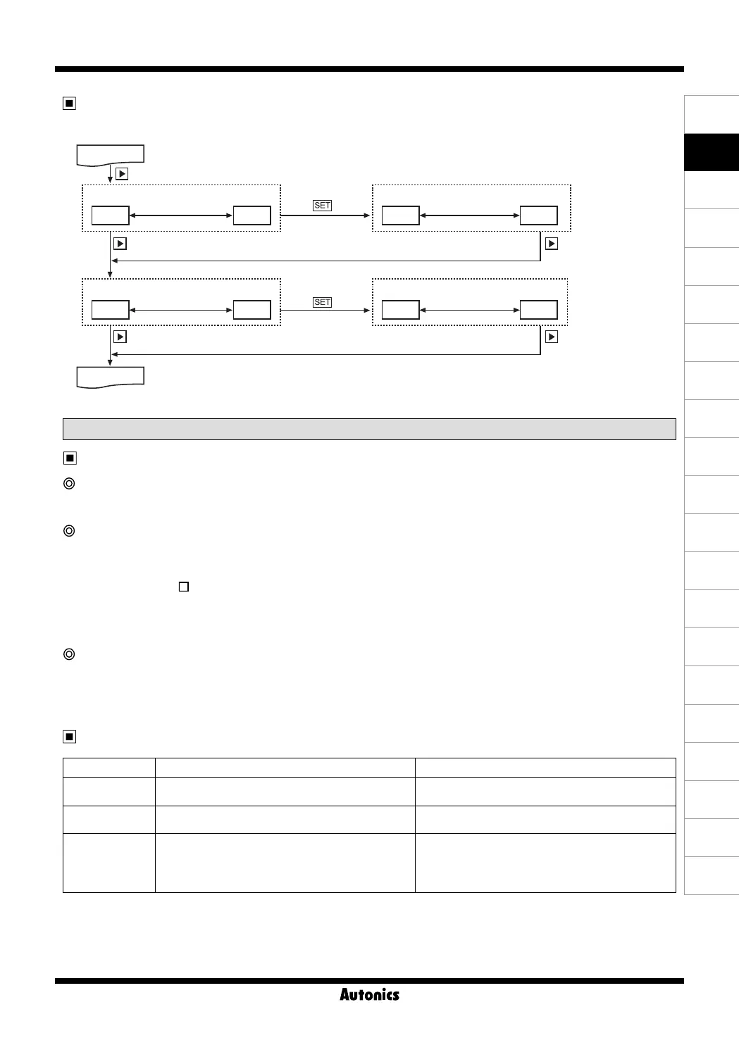
Dual display / Single display common features
Program mode function
Amplifier units connection using side connector
In case multiple amplifier units are connected, the power supply for one unit will feed all connected units.
Auto channel setting function
● The channel for each amplifier unit - connected by side connector - is automatically set in a certain direction ( →) as soon
as power is supplied. Channel number is increasing one by one.
● Auto set channel can be checked in channel parameter in program mode.
● In case of BF5R-S1- , auto set channel can be checked only when initial power is supplied. (Not available afterwards).
● Channel range : 1 to 32(applied the same to all models)
※
Note that auto set channel cannot be changed and the channel No. of each amplifier unit is not saved in case of
power OFF.
Mutual interference prevention function
A function to set different light receiving time for each amplifier unit in case of adjacent fiber cable installations in order to
prevent mutual interference occurring. (Set automatically when power is turned ON.)
※
Mutual interference function is allowed up to maximum 8 amplifier units regardless of the unit model and response time.
High peak, low peak function
A function to monitor the high/low peak value of incident light level. The monitored high/low peak value can be initialized.
Error code Cause Troubleshooting
ERRL
In case incident light level is below the min. range when
teaching.
Increase the incident light level above min. range.
ERR
In case overcurrent inflow occurs into output circuit. Remove overcurrent due to overload.
ERB
● In case Slave is failed to execute Master's instructions
due to unstable communication line connection during
Group Copy / Load / Save / Teaching.
● In case other communication errors occur
● Check amplifier unit's connection again.
● Check circuit and hardware around side connector.
Error code
※
If there are no key operations within 60 sec.,
it is returned to RUN mode.
RUN mode
RUN mode
(P) for 3sec.
Press
Initialize to current
incident light level
Initialize to current
incident light level
Both parameters
flash every 0.5 sec.
Both parameters
flash every 0.5 sec.
Both parameters
flash every 0.5 sec.
Both parameters
flash every 0.5 sec.
High peak
Low peak
High peak
Low peak
Max. incident
light level
Min. incident
light level
Max. incident
light level
Min. incident
light level
HPEK
LPEK
HPEK
LPEK
4000
1000
3000
950
 Loading...