B-10
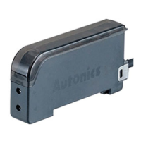
BF5 Series
10
9.5
2-ø2.4
6
2
16
36.5
72
30
6.7
9.9
①
②
①
※
35mm DIN rail
①
②
③
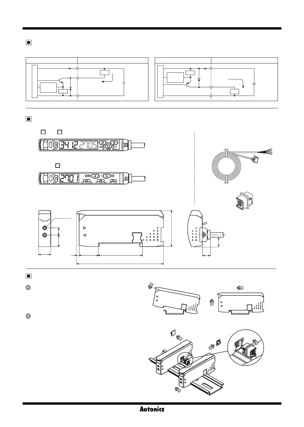
Dimensions
(unit: mm)
● BF5 -D1-
● Accessories
● BF5R-S1-
●
Connector type wire(length: 2m)
●
Side connector
[Installation] [Removal]
Installations
Amplifier unit mounting
● Installation: Hang up the backside holder on the DIN rail
and press the unit toward the DIN rail.
● Removal: Slide the back part of the unit as the
①
figure
and lift up the unit as the
②
figure.
Amplifier unit connection
● Remove the side cover at the connecting side as the
figure
①
and connect the side connector as the figure
②
.
● After mounting the unit on the DIN rail, push gently
both units to fasten each other.
※
Make sure that connections between the unit case
and connectors correctly. Improper connection may
cause malfunction of channel setting and mutual
interference prevention functions.
※
Do not supply the power while connecting / disconnecting
amplifier units.
Control output diagram
● NPN open collector output ● PNP open collector output
Fiber optic sensor circuit Connection
+
-
(Brown)+V
(Black)output
(Blue)0V
Over
current
protection
Max.100mA
12-24VDC
±10%
Load
Main circuit
Load
Fiber optic sensor circuit Connection
(Brown)+V
(Black)output
(Blue)0V
Max.100mA
12-24VDC
±10%
Load
Main circuit
Over
current
protection
+
-
Load
 Loading...