Item
Insulation resistance
Dielectric strength
Initial contact resistance
Mating/unmating force
Mating cycles
Connector nut tightening torque
Cable pullout strength
Vibration resistance
Impact resistance
Protective structure
Ambient operating temperature
Ambient storage temperature
Ambient operating humidity
Material Contacts:
Min. 0.8 N
·
m *2
0.4 to 4.0 N per contact
50
10 to 55 Hz, 1.5 mm peak-to-peak amplitude, for 2 hours each in X, Y and Z directions
300 m/s
2
, 3 times each in X, Y and Z directions
IP67
–10 to +70˚C
–20 to +80˚C
Max. 95% RH
Note 1: Specifications assume Azbil male/female connectors.
Note 2: The recommended torque is 0.4 to 0.6 N-m. If fastened poorly, the IP67 protection is lost, or looseness occurs. Fasten the connector securely by hand.
Gold-plated brass
Contact holder: Glass-lined polyester resin
Housing: Polyester elastomer
Coupling: Ni-plated brass
O-ring: NBR
Specifications
Max. 100 MΩ(by 500 Vdc megger)
1,500 Vac for 1 minute (between contacts, and between contact and connector housing)
Max. 40 mΩ(with 3A current to connected male and female connectors.
Semiconductor lead-specific resistance not included.)
Min. 100 N
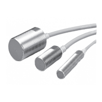
CONNECTOR SPECIFICATIONS
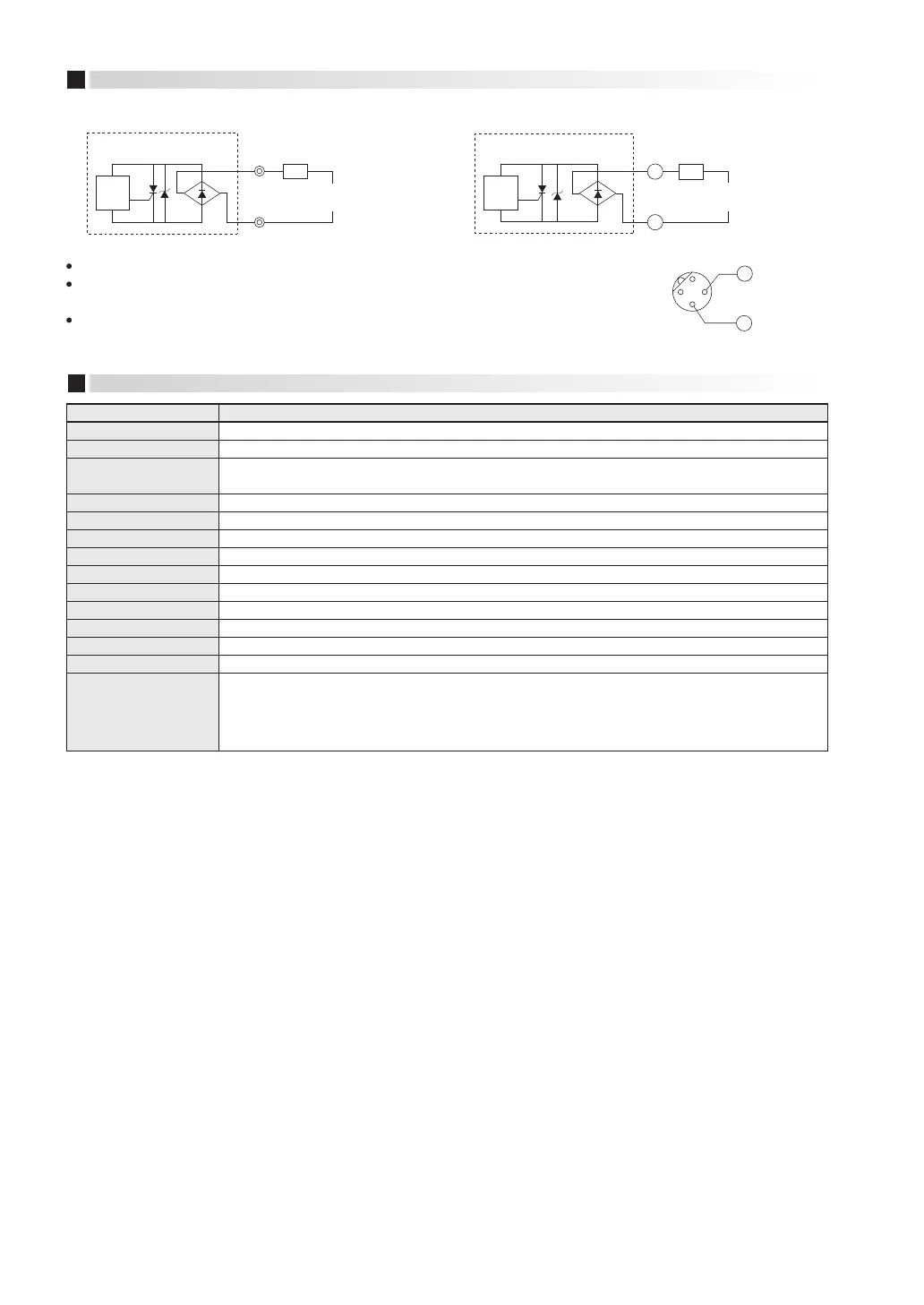
*1
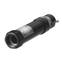
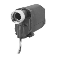
Preleaded type Preleaded connector type
The load may be connected to either pole.
The LED operates normally during a load short circuit,
so check the wiring if the output is wrong.
Fasten connectors tightly by hand.
40 to 250 Vac
20 to 250 Vdc
Brown
Blue
Load
Main
circuit
40 to 250 Vac
20 to 250 Vdc
Connector
Load
Main
circuit
3
4
3
4
5 6
 Loading...