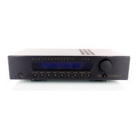
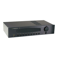
Here is a typical preamplifier to amplifier setup:
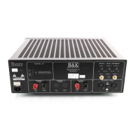
OUTPUTS
Five way binding posts are provided. There is one pair provided for each channel. They
are designed to accept a banana-type plug, spade-lug connector (shown below), terminal
posts, and bare wire, and they are color coded for easy identification. The positive (+)
post should always be connected to the speakers (+) jack. The negative (-) post should
always be connected to the speakers (-) jack.
Spade connector Banana jack
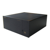
Here is a typical amplifier output setup:
Page 6
P/N 13009 Rev.0102
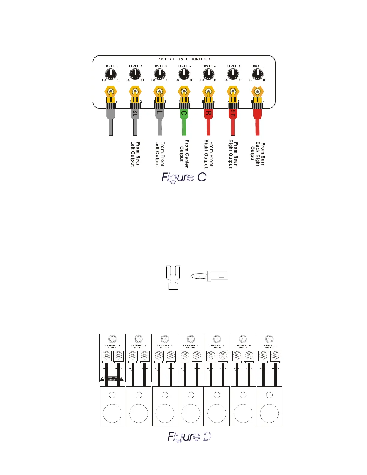
8=?DCB ;4E4; 2>=CA>;B
;4E 4;
;> 7 8
;4E 4; !
;> 78
;4E 4; "
;> 78
;4E 4; #
;> 7 8
;4E 4; %
;> 7 8
;4E 4; $
;> 7 8
8=?DC 8=?DC ! 8=?DC " 8=?DC # 8=?DC $ 8=?DC %
;4E4; &
;> 78
8=?DC &
R
From Front
Right Output
From Front
Left Output
L
SR
From Rear
Right Output
SL
From Rear
Left Output
C
From Center
Output
From Surr
Back Right
Output
SBL
SBL
From Surr
Back Left
Output
20DC 8 > =
?;DB
<8=DB
>DC?DC
270= =4 ; %
>DC?DC
270= =4 ; &
?;DB
<8=DB
>DC?DC
270= =4 ; $
?;DB
<8=DB
>DC?DC
270= =4 ; #
?;DB
<8=DB
>DC?DC
270= =4 ; "
?;DB
<8=DB
>DC?DC
270= =4 ; !
?;DB
<8=DB
>DC?DC
270= =4 ;
?;DB
<8=DB
 Loading...