7110102.03 (1-06/13) 38
INSTALLER Section (en)
F37 Factory setting 003 F59 Factory setting 005
F38 Factory setting 000 F60 Factory setting 120
F39 Factory setting 067 F61 Factory setting 015
F40 Factory setting 070 F62 Factory setting 030
F41 Factory setting 010 F63 Factory setting 025
F42 Factory setting 042 F64 Factory setting 000
F43 Factory setting 001
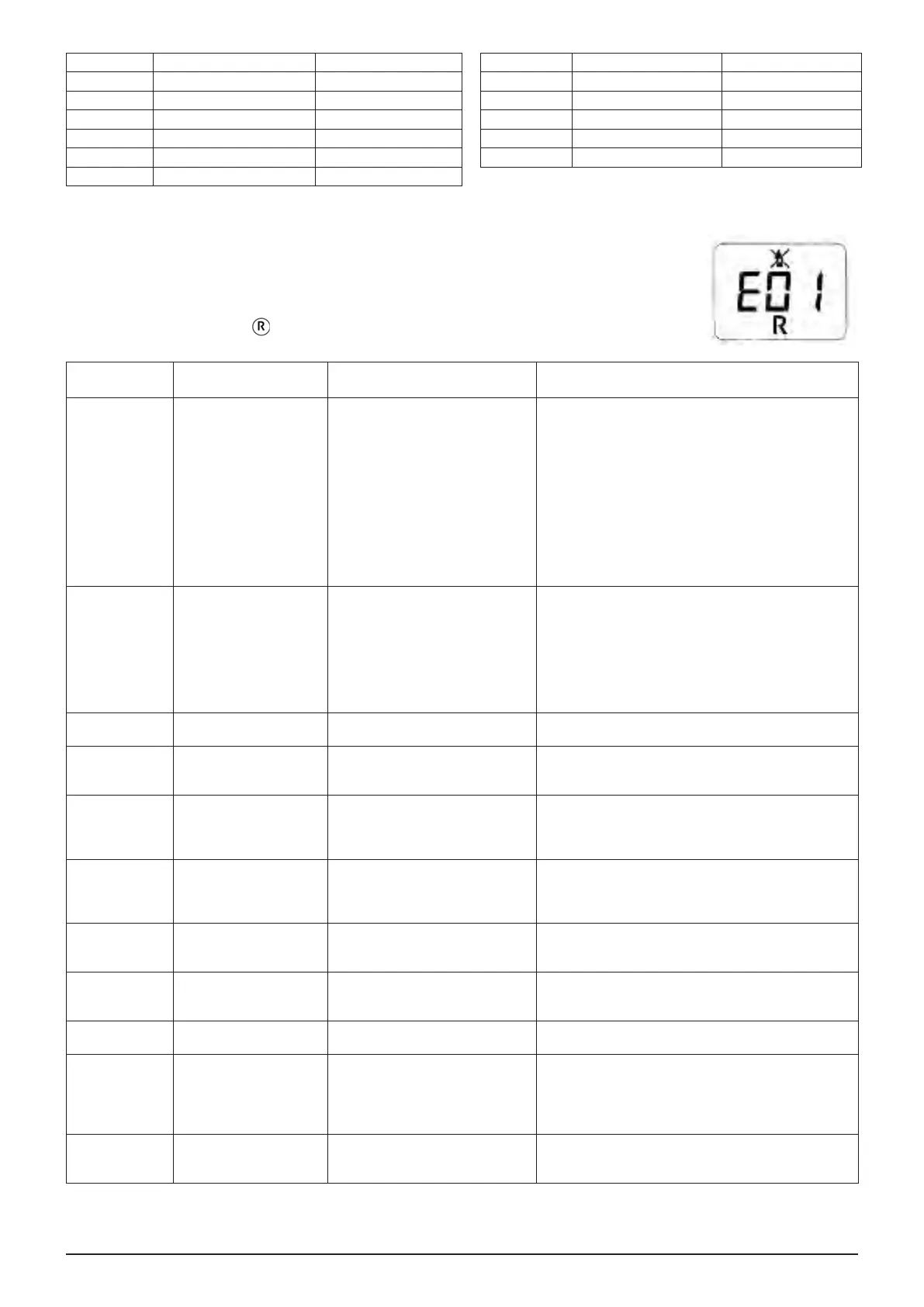
15. TROUBLESHOOTING SERVICE FAULTS
The faults shown on the display are identied with the symbol "E" and a number (fault code). For a
complete list of faults, see the following table.
If "R" appears on the display the fault must be RESET by the user.
To reset, press and hold down for at least 2 seconds. If this fault persists, call the Authorised Service
Centre.
CODE
DISPLAYED
FAULT POSSIBLE REASON SERVICE ACTION
E01 Shut down for ignition
failure.
• No inlet gas pressure.
• Ignition switch-ame sensor wire
interrupted.
• Flame sensing electrode faulty or
incorrectly positioned.
• Gas valve faulty.
• Electronic board faulty.
• Check that the gas valve is open and there is no air in
the gas supply circuit.
• Check the gas supply pressure.
• Check the wire is uninterrupted and makes good
contact with the ame sensing electrode and the
ignition switch.
• Check the connections between the gas valve and the
electronic board.
• Check the ame sensing electrode is in good
condition and in the right position (see the
POSITIONING THE IGNITION AND FLAME-
SENSING ELECTRODE section).
E02 Shut down by safety
thermostat.
• No water in the primary circuit
(pump blocked or exchanger
obstructed).
• Limit thermostat faulty.
• Limit thermostat wiring
interrupted.
• CH ow NTC probe faulty.
• Electronic board faulty.
• Check pump operation (unscrew the front cap and
release the pump impeller with a screwdriver).
• Check the pump power input wiring.
• Check that the limit thermostat is undamaged and
replace it if necessary.
• Check the continuity of the limit thermostat wiring.
• Check the CH ow NTC probe (*).
• Check whether the exchanger is clogged.
E03 Board conguration error. • Parameter F43 has not been set
correctly.
• Set parameter F43 with the value indicated in the
table in the SETTING PARAMETERS section.
E04 Safety error due to
ignition failure or frequent
ame loss.
• See the reasons indicated in E01.
• See the reasons indicated in E42.
• See the actions indicated in E01.
• See the actions indicated in E42.
E05 Flow sensor failure. • CH ow NTC probe faulty (circuit
open or shorted).
• CH ow probe wiring interrupted
or shorted.
• Check the CH ow NTC probe (*).
• Check the continuity of the CH ow probe wiring.
• Make sure the wiring has not shorted.
E06 DHW sensor fault. • DHW ow NTC probe faulty
(circuit open or shorted).
• DHW ow probe wiring
interrupted or shorted.
• Check the DHW NTC probe (*).
• Check the continuity of the DHW probe wiring
• Make sure the wiring has not shorted.
E07 Fumes NTC probe fault. • Fumes NTC probe faulty (circuit
open).
• Fumes probe wiring interrupted.
• Check the fumes NTC probe (**).
• Check the continuity of the fumes probe wiring
E08 Error in the ame
amplication circuit.
• The electronic board is not
earthed.
• Electronic board faulty.
• Check the continuity of the earth connections between
the electronic board (X4 connector) and the power
supply terminal block.
E09 Error in the gas valve
safety circuit.
• Electronic board faulty. • Replace the electronic board.
E10 No hydraulic pressure
switch enable.
• CH circuit pressure < 0.5 bar
• Hydraulic pressure switch faulty.
• Hydraulic pressure switch wiring
faulty.
• If the pressure in the CH circuit is < 0.5 bar, perform
lling (see the FILLING THE SYSTEM section).
• Check the hydraulic pressure switch works correctly.
• Check the continuity of the hydraulic pressure switch
wiring
E22 Switching off due to power
supply reductions.
• Supply voltage V < 162V
(automatic reset at V> 168V)
• Electronic board faulty.
• Check whether the power supply reductions are due
to reasons other than the boiler. If so, contact the
electricity provider.
 Loading...