10.0 Installation
29
© Baxi Heating UK Ltd 2006
Check Site Requirements (section 7) before
commencing.
10.1 Initial Preparation
The gas supply, gas type and pressure must be
checked for suitability before connection (see Section
7.4).
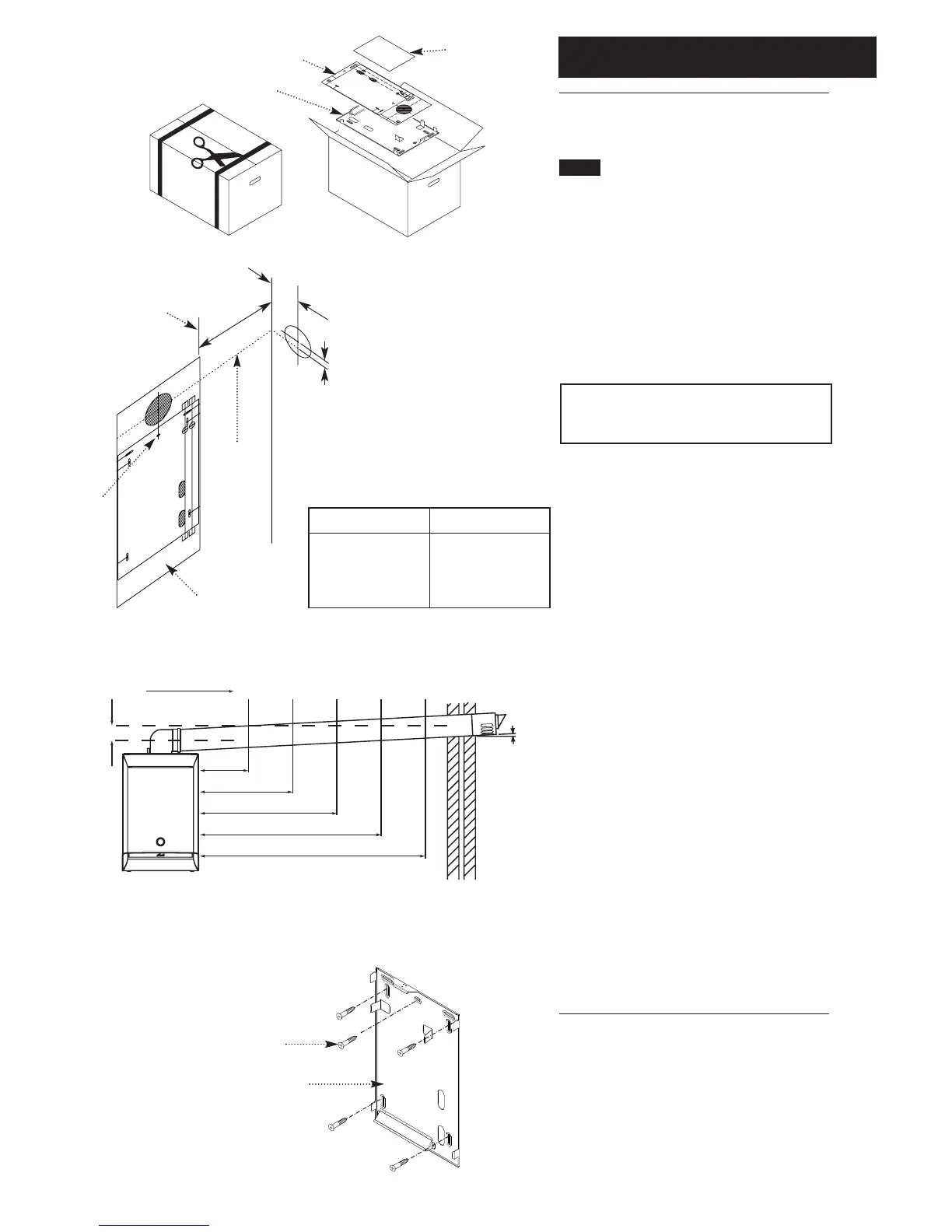
1. Cut the banding and remove the fixing template, wall
plate and literature pack (Fig. 19a) from the carton.
2. After considering the site requirements (see Section
7.0) position the template on the wall ensuring it is level
both horizontally and vertically.
NOTE: When fitting Plume Displacement Kit refer
to the instructions supplied for details of
installation of the flue.
3. Mark the position of the centre hole for the wall
plate (Fig. 20).
4. Mark the centre of the flue hole (rear exit).
For side exit: project the horizontal side flue centre line
into the corner of the room and along the wall to
where the flue hole will be drilled. (Fig. 20).
The diagram (Fig. 21) shows the dimensions required to
ensure any horizontal flue is installed with the correct
fall to the boiler. Mark the offset (V) dimension and if
required, mark the position of the gas and water pipes.
Remove the template.
5. Cut the hole for the flue (minimum diameter
127mm, see table (Fig. 20) for wall thicknesses and flue
diameters).
6. Drill and plug the wall as previously marked. Secure
the wall plate using the centre hole (Fig. 22).
7. Ensuring the wall plate is level both horizontally and
vertically, drill and plug at least 4 securing positions at
the top and bottom through the wall plate. Utilising the
slots available ensure the wall plate is square and secure
to the wall (Fig. 22).
8. Loosely route the condensate discharge pipe to the
lower left hand side of the wall plate.
Wall Thickness
up to 227mm
up to 750mm
up to 1200mm
Flue Hole ø
127mm core drill
150mm core drill
175mm core drill
Fig. 20
Fig. 21
Fig. 22
Horizontal
Side Flue
Centre Line
EXAMPLE: Boiler is 2 metres away
from corner of wall, flue duct hole is
55mm up from horizontal side flue
centre line. This will maintain the
approx 1.5° backfall to the boiler.
Wall Plate Template
Wall Plate
Edge of Boiler
Centralising
Screw
 Loading...