<t
Cl
0
CXl
CXl
>
0
09/80
Secondary
and
Omnidirectional Antenna
Diagrams
This side lobe suppression
is
permitted
by
comparing the amplitudes
of
the
pulses
P1
and
P2.
As
can
be
seen
from
the antenna pattern, power received
by
the transponder
from
the omnidirectional antenna
is
less
than
that
from
the main lobe,
but,
in this
case,
is
higher than the power
of
the side lobes
of
the
secondary antenna.
And
thus main lobe interrogation occurred when Pl
is
larger than
P2,
side lobe inter-
rogation when
P2
is
larger than
P1.
Side
lobe
Interrogation
From
the
above diagram
it
will
be
seen
that
the transponder provides no reply when
P2
is
~
P1.
Whereas
it
provides a
response
wh
en
P2
is
<
(P1
- 9 dB).
1 n the intermediate grey zone
of
0
to
- 9 dB a
response
may occur
or
not
occur.
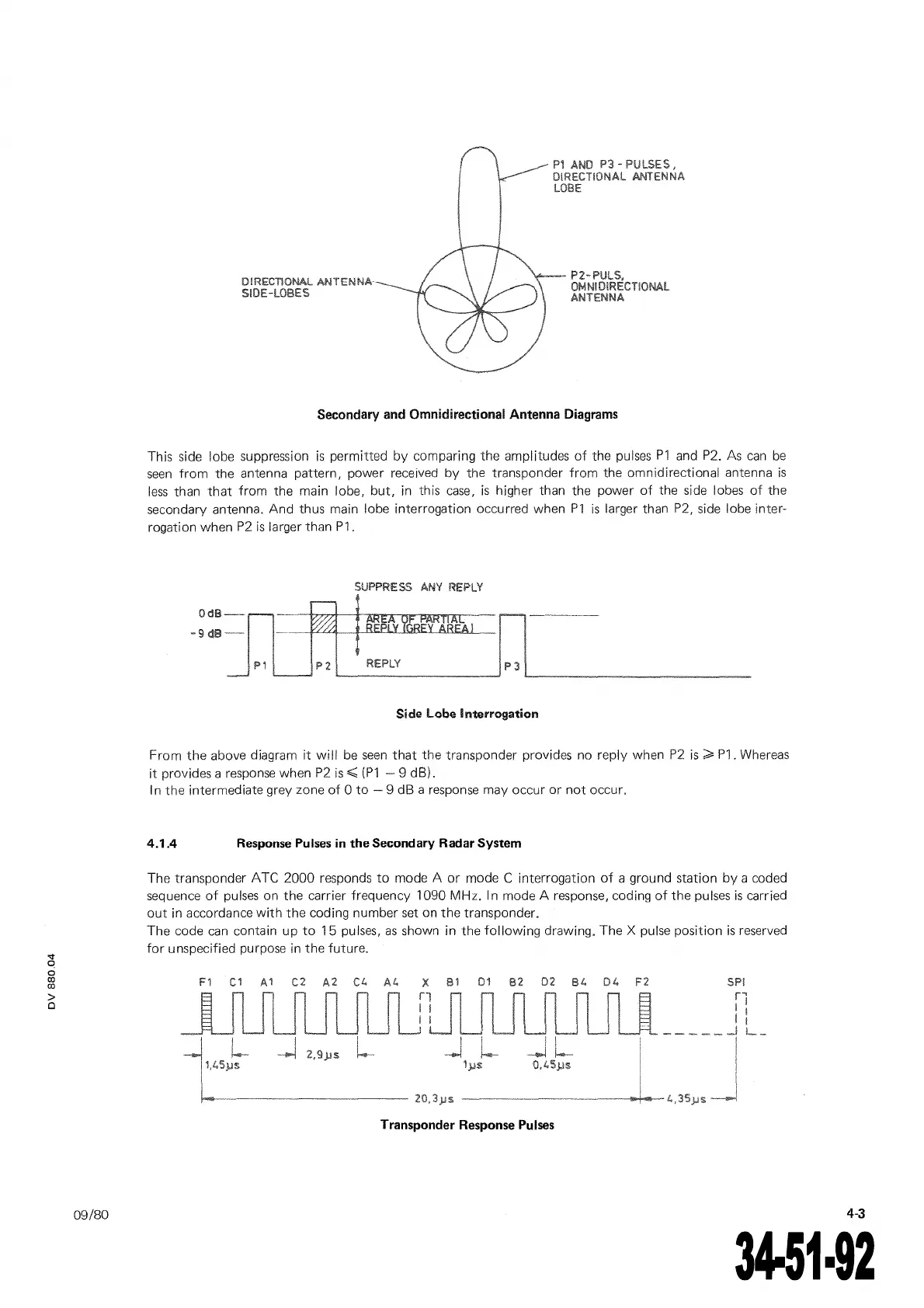
4.1.4
Response
Pulses
in
the
Secondary Radar System
The transponder ATC 2000 responds
to
mode A
or
mode C interrogation
of
a grou
nd
station
by
a coded
sequence
of
pulses
on the carrier frequency 1090 MHz. 1 n mode A response, coding
of
the pulses
is
carried
out
in accordance
with
the
coding number set on the transponder.
The code
can
contain up
to
15
pulses,
as
shown in the
following
drawing. The X pulse position
is
reserved
for
unspecified purpose in the future.
Transponder
Response
Pulses
4-3
The document reference is online, please check the correspondence between the online documentation and the printed version.
 Loading...