<t
q
0
co
co
>
Cl
4.1.5 Primary
and
Secondary
Signal
Display
on
the Radar Screen
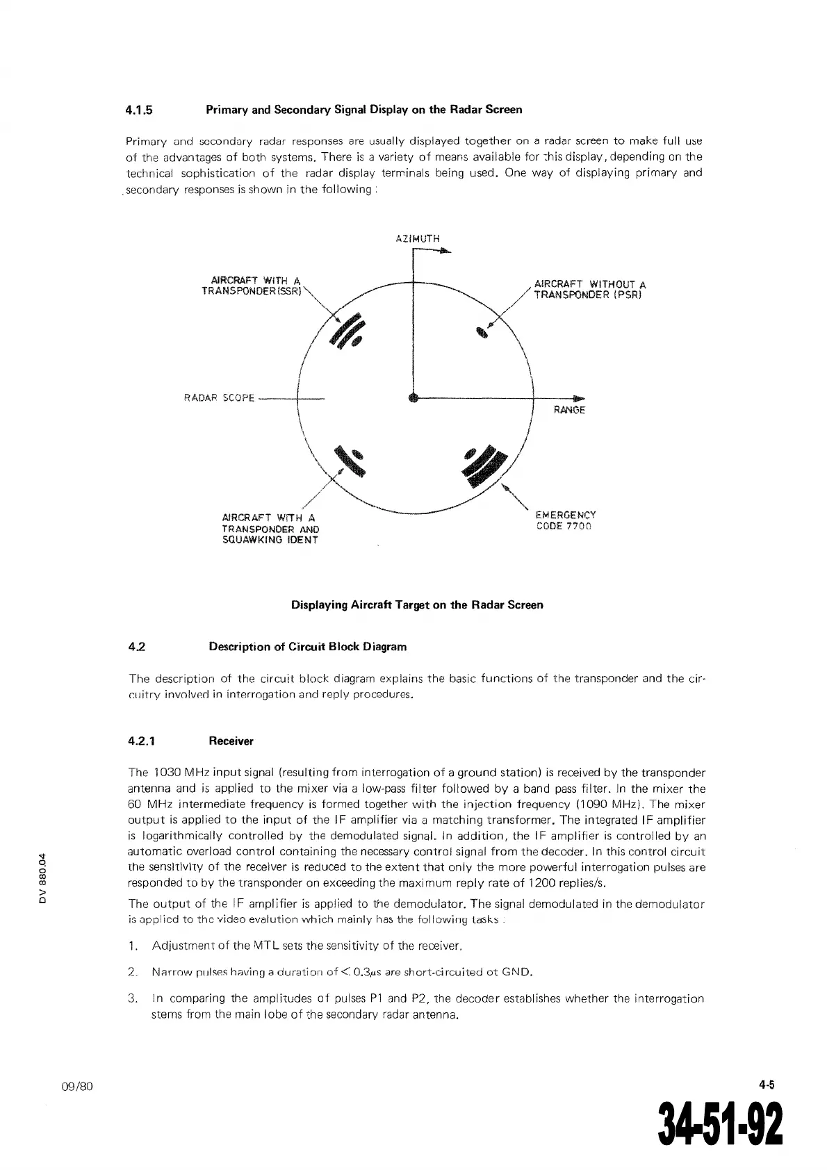
Primary
and sccondory radar responses
are
usually displayed
together
on a radar screen
to
make full
u~e
of
the advantages
of
both systems. There
is
a variety
of
means available for
:his
display, depending
on
the
technical sophistication
of
the radar display terminais being used. One way
of
displaying primary
and
. secondary responses
is
shown in the
following
.
AJRCRAFT
WITH
A
TRANSPONOER
(SSRI"'
AJRCRAFT
W!TH
A
TRANSPONDER
AND
SOUAWKING
!DENT
AZIMUTH
AIRCRAFT WITHOUT A
//
TRANSF()NOER (PSRl
EMERGENCY
CODE
7700
Displaying Aircraft Target
on
the Radar Screen
4.2 Description of Circuit Block Diagram
The description
of
the
circuit
block
diagram explains
the
basic
functions
of
the transponder and the cir·
cuitry
involvP.rl in interrooation and reply procedures.
4.2.1
Receiver
The 1030 MHz
input
signal (resulting
from
interrogation
of
a grou
nd
station)
is
received
by
the transponder
antenna and
is
applied
to
the
mixer
via a low-pass
filter
followed
by
a band
pass
filter.
ln the
mixer
the
60
MHz
intermediate frequency
is
formed together
with
the
injection
frequency (1090 MHz). The
mixer
output
is
appl ied
to
the
input
of
the 1 F amplifier via a
matching
transformer.
The integrated 1 F
amplifier
is
logarith mically controlled
by
the demodulated signal.
ln
addition,
the 1 F
amplifier
is
control led
by
an
automatic
overload
control
containing the necessary
control
signal
from
the
decoder. ln this control
circuit
the sensitiviry ot the receiver
is
reduced
to
the
extent
that
only
the
more powerful interrogation pulses are
responded
toby
the transponder on exceeding the maximum
reply
rate
of
1200 replies/s.
The
output
of
the IF
amplifier
is
applied to the demodulator.
The
signal demodulated in the
demodulator
is
applicd
to
the video evalution
which
mainly
ha5
the follovving
la5k::;.
1.
Adjustment
of
the
MTL
sets
the
sensitivity
of
the receiver.
2.
NF1rrnw
Jli!ISP.S having a
duration
of<
0.3,us
are
short-circuited
ot
GND.
3.
ln
comparing the amplitudes
oi
pulses
Pl
and
P2, the decoder establishes whether the interrogation
stems from the main lobe
of
the secondary radar antenna.
The document reference is online, please check the correspondence between the online documentation and the printed version.
 Loading...