EasyManuals Logo
Home>Beckhoff>Servo Drives>AX5112

Beckhoff AX5112 Startup Manual

Beckhoff AX5112
46 pages
To Next Page IconTo Next Page
To Previous Page IconTo Previous Page
Page #23 background imageLoading...
Page #23 background image
BECKHOFF Drive Technology 4 Product description
AX5000 Version : 4.5 23
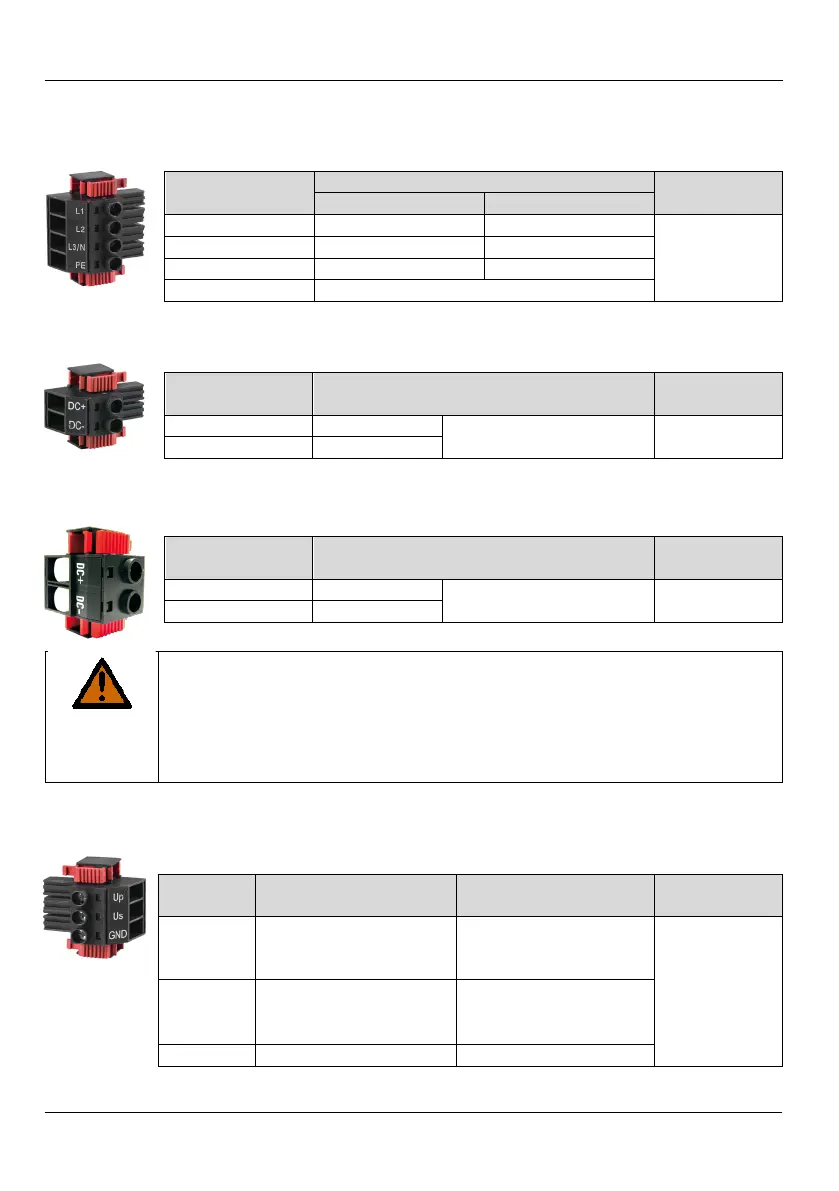
4.7 Overview of connectors/terminal points
4.7.1 X01 - wide voltage input
Terminal point
Connection
Tightening
torque
3-phase
1-phase
L1
Phase L1
Phase L1
0,5 -0,6 Nm
L2
Phase L2
not used
L3/ N
Phase L3
Neutral conductor
PE
Protective conductor
4.7.2 X02 - DC link (AX5101 - AX5125 und AX520x)
Terminal point
Connection
Tightening
torque
DC+
DC link +
external brake resistor
and drive system
0,5 -0,6 Nm
DC
DC link
4.7.3 X02 - DC link (Only AX5140)
Terminal point
Connection
Tightening
torque
DC+
DC link +
only for drive system 1,2 -1,5 Nm
DC
DC link
WARNING
Serious risk of injury through high electrical voltage!
890 V DC voltage at the DC link terminals. Dangerous voltage may be
present for 5 minutes after the device is switched off.
Remove the connector only if you want to build a drive system with a AX-
Bridge.
Remove the white hexagon plugs only if you wire the terminal points again.
4.7.4 X03 - 24 V
DC
supply
Terminal
point
Connection
Current
consumption
Tightening
torque
U
p
+
24 V
DC -0/+25%
- periphery
(e.g. separate braking
voltage)
Depending on the
connected consumers
(see X06 and X14,X24)
0,5 0,6 Nm
U
s
+
24 V
DC
±
25%
- system
supply (depending on
rated current)
-12 A = 0.4 A – 0.8 A
18 A - 25A = 1,1 A
40 A = 1,6 A
GND
GND

Table of Contents

Other manuals for Beckhoff AX5112

Questions and Answers:

Question and Answer IconNeed help?

Do you have a question about the Beckhoff AX5112 and is the answer not in the manual?

Beckhoff AX5112 Specifications

General IconGeneral
BrandBeckhoff
ModelAX5112
CategoryServo Drives
LanguageEnglish

Related product manuals