EasyManuals Logo
Home>Beckhoff>Servo Drives>AX5112

Beckhoff AX5112 Startup Manual

Beckhoff AX5112
46 pages
To Next Page IconTo Next Page
To Previous Page IconTo Previous Page
Page #27 background imageLoading...
Page #27 background image
BECKHOFF Drive Technology 4 Product description
AX5000 Version : 4.5 27
AX5000-xxxx-0200 (Hardware 2)
Terminal point
Connection
Output current
T-
OCT and temperature
T+
OCT + and temperature
PE
Signal pair screen
B-
Brake GND
B+
Brake (U
p
) +
2.2 A max.
Note
Output current
The specified output current is the maximum value. The actual value
depends on your current configuration.
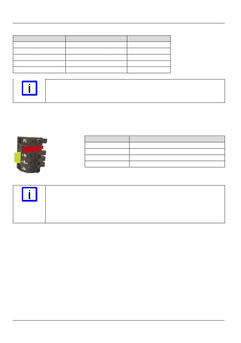
4.7.12 X07 – internal and external brake resistor
(Only AX5140)
Terminal point
Connection
PE
Protective conductor
+ R
B
External brake resistor +
+ R
Bint
Internal brake resistor +
– R
B
Brake resistor GND
Note
Operation of AX5140
Commissioning the AX5140 can only be carried out when the terminal
points "+R
Bint
" and "+R
B
" are bypassed (delivery state) or an external brake
resistor is connected (terminal points "+R
B
" and "-R
B
"). If these measures
are not taken then the AX5140 will be stopped with the error message
"FD4B undervoltage"

Table of Contents

Other manuals for Beckhoff AX5112

Questions and Answers:

Question and Answer IconNeed help?

Do you have a question about the Beckhoff AX5112 and is the answer not in the manual?

Beckhoff AX5112 Specifications

General IconGeneral
BrandBeckhoff
ModelAX5112
CategoryServo Drives
LanguageEnglish

Related product manuals