BECKHOFF Drive Technology 4 Product description
AX5000 Version 6.2 29
*) Switch, KTY 83-1xx or KTY 84-1xx
AX5000-xxxx-0200 (Hardware 2)
Connection
0.2 – 1.5 mm
2
0.2 – 0.25 Nm
The specified output current is the maximum value. The actual value
depends on your current configuration.
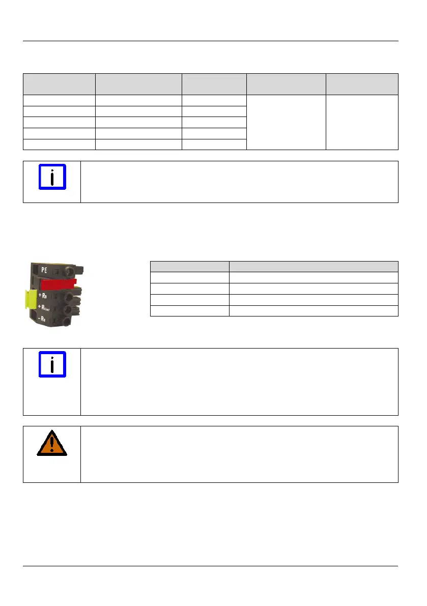
4.7.12 X07 – internal and external brake resistor
(Only AX5140)
External brake resistor +
Internal brake resistor +
Note
Commissioning the AX5140 can only be carried out when the terminal
points "+R
Bint
" and "+R
B
" are bypassed (delivery state) or an external brake
resistor is connected (terminal points "+R
B
" and "-R
B
"). If these measures
are not taken then the AX5140 will be stopped with the error message
WARNING
Serious risk of injury through high electrical voltage!
875 V DC voltage at the brake terminals X07. Dangerous voltage may be
present for 15 minutes after the device is switched off. Measure the voltage
at the brake contacts +R
B
und -R
B
. The device is safe once the voltage has
 Loading...


