Diagnostics and error handling
BK3xx0 61Version: 4.3.0
6 Diagnostics and error handling
6.1 LEDs
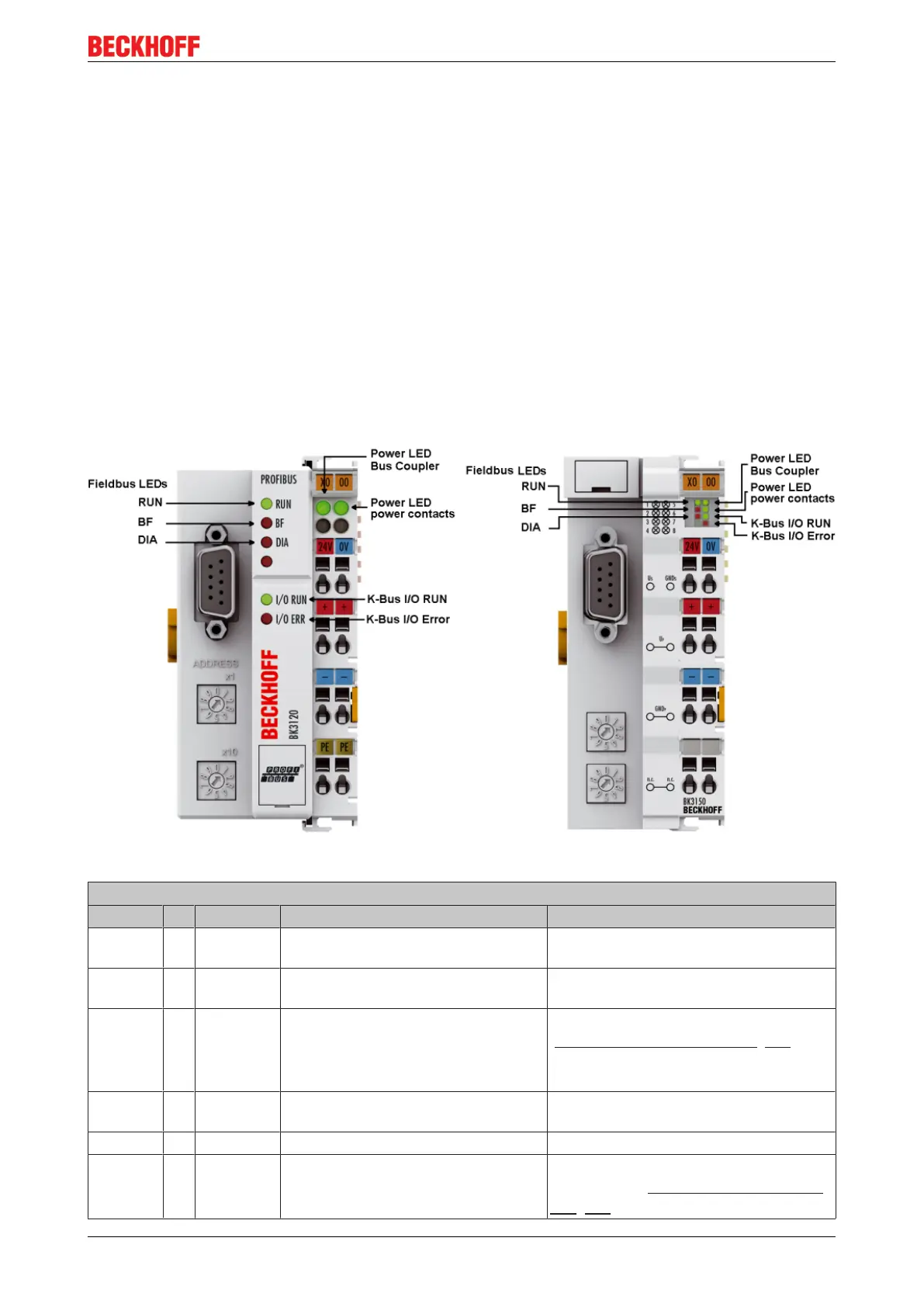
The Bus Coupler has two groups of LEDs for the display of status. The upper group (BK3xx0) or left hand
group (LC3100) indicates the state of the fieldbus.
On the upper right hand side of the BK3xx0 Bus Coupler are two more green LEDs that indicate the supply
voltage. The left hand LED indicates the presence of the 24V supply for the Bus Coupler. The right hand
LED indicates the presence of the supply to the power contacts. The two K-Bus LEDs (I/O RUN, I/O ERR)
are located under the fieldbus LEDs. These indicate the operational state of the Bus Terminals and the
connection to these Bus Terminals.
Fieldbus LEDs
The upper three LEDs (or the two LEDs on the left) indicate the operating state of the PROFIBUS
communication:
Fig.44: LEDs BK3120 and BK3150
BK3xx0
I/O RUN BF DIA Meaning Remedy
on off off Operating state: RUN, inputs are read
and outputs are set
Everything is operating correctly
on on off, blinking 1. Bus activity, but slave is already
parameterized
Start master
2. Bus error with reaction to
PROFIBUS error:
a.) K-bus outputs become 0 or b.) K-
bus outputs are retained
Check parameters, configuration
(possible error in DP start-up [}67])
off off off Data exchange with the master is not
started
PLC start
off on on No bus activity Start the master, check the bus cable
off on off, blinking Bus error with reaction to PROFIBUS
error: K-bus cycle is stopped
Start master, check parameters,
configuration (possible error in DP start-
up [}67])
 Loading...