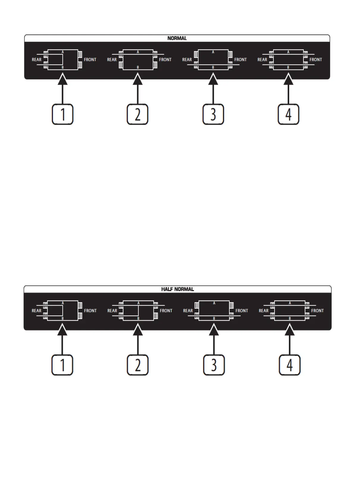
NORMAL MODE
In NORMAL mode the rear A & B jacks of the channel are connected together (pos. (1)). The connection between the
rear jacks is disabled when you insert a cable into jack A or B on the front panel (pos. (2) and (3)).
In the example above, top-row channels 1 to 4 are from the outputs of a keyboard and a MIDI sound module.
They are connected, in this example configuration, to input channels 1 to 4 on the mixer.
Channels 5 and 6 are from the subgroup outputs of a mixer and are connected, in this example configuration, to the
inputs of a computer audio card. Audio sequencer software records the music signals directly onto the hard disk of
the computer. Channels 7 and 8 connect the soundcard outputs to the 2-track inputs of the mixer. Since the rear-
panel jacks are connected together in the Normal mode (pos. (1)), the subgroup signals can be recorded directly onto
the PC and played back via the 2-track input of the mixer (playback/monitoring), without a single patch cable having
to be plugged in! In this way, you can build up a basic configuration for your studio, which can be easily modified by
simply patching signals via the front-panel jacks
(pos. (2)) or by feeding in external signals via patch cables (pos. (3)). You could, for example, connect the keyboard
signal to channels 3 and 4 by patching 1A to 3B, and 2A to 4B. So, before wiring your studio, it is advisable to identify
the connections that will be used most frequently and set them up, as your basic configuration, one above the other
on the patchbay. Then you will have a clear overview of all connections and still be flexible.
HALF-NORMAL MODE
In HALF NORMAL mode, the rear A & B jacks of the channel are connected together (pos. (1)). Unlike NORMAL
mode, the connection between the rear-panel jacks is not disabled when a 1/4″ plug is inserted into jack A on the
front panel
(pos. (2)). This allows you to take the signal from a mixers channel strip in parallel—without interrupting the signal
path on the channel strip. Like NORMAL mode, the connection between the rear-panel jacks is disabled when a 1/4″
plug is inserted into jack B on the front panel (pos. (3)). When 1/4″ plugs are inserted into both jacks A & B on the
front panel, the front jacks will be connected separately to the corresponding rear jacks (pos. (4)). This is called an
“input break” and is used mainly to insert an effect or processor into the signal path.
In the example above, top-row channels 9 to 14 are the sends (tip contact of insert points) from mixer channels 1 to 4
plus the main left & right sends. They are connected, in this example configuration, to their respective returns (ring
contacts of insert points) of the mixer.
 Loading...