13
EN
ARC CONTROL UNIT
IMPORTANT, PLEASE READ CAREFULLY:
The radio receiver in this product is compatible only with the new ARC (Advanced Rolling Code) transmitters which, thanks to 128-bit encryption ensure
superior copy-security.
Storing new ARC transmitters is quite similar to that of normal rolling code transmitters with HCS coding
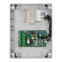
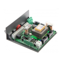
1) LOGICA CONTROL UNIT
1.1) WIRE DIAGRAM
Wire connections shown in Fig. 1 are described hereunder:
Terminal Function Description
L-N-GND Power supply Input, 230VAC 50Hz (1-Phase/2-Neutral)
BLINK
Flashing light Connection of flashing light, 230Vac 40W max.
MOT-COM-MOT Motor 1/2
Connection to motor 1/2 : (6-speed/7-Com/8-speed)*
Should 2 motors be used, connect the second motor in parallel.
SER L Service light Connection to the courtesy light 24Vdc (LED.ZED accessory or LED.SC panel connection).
COM COM Common for limit switch and all control inputs.
SW1 SWO Input, OPEN limit switch (N.C. contact)
SW2
SWC Input, CLOSE limit switch (N.C. contact)
STOP STOP Input, STOP push button (N.C. contact)
PHOT
PHOT
Input, connection to safety devices, N.C. contact
(e.g. Photocells)
CLOSE CLOSE Input, CLOSE push button (N.O. contact)
PP Step-by-Step Input, step-by-step push button (N.O. contact)
24 Vac 24 Vac Output, power supply of accessories, 24Vac/1A max.
AUX AUX Normally Open (N.O.) contact, not powered, configurable as SCA/II°CH/PHOTO TEST.
BAR
COSTA
Input, safety edge contact
Resistive edge: Closed “DAS” jumper
Mechanical edge: Open “DAS” jumper
If the safety edge is activated in the opening phase, the gate stops.
In the closing phase, the gate stops and the performs a movement reversion (opens) for 3s.
ANT-SHIELD Aerial Connection to the radio receiver card of the aerial (SHIELD-screen/A NT-signal).
CM-CM Capacitor Connected to motor capacitor
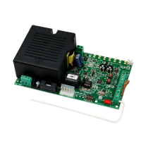
J2 Radio receiver
Built-in radio receiver.
The radio receiver in this product is compatible with the ARC (Advanced Rolling Code) transmitters, with
433.92 MHz frequency.
ENC1 Encoder Fast connector for encoder connection (ZED Encoder version only)
MF3/8/4
Primary
Transformer
Connection, winding of primary transformer
Warning: The Faston on the transformer connected to terminal MF8 (TORQ) set the torque applied to
motor.
See section “To adjust the motor power ”.
J6 N/A Not available
MF7/MF5/MF6
Secondary
Transformer
Connection, winding of secondary transformer
IMPORTANT:
Should two motors be used, connect the limit switches of one single motor to the control unit.
The connection between 1 motor ZED.AUTR and 1 motor ZED.SC is shown in Fig.3.
The connection between 1 external control unit (LOGICA 7B) and 2 motors ZED.SC is shown in Fig.4.
1.2) FUSES
F1 Output protection fuse of accessories and signals (T500mA)
F3 Motor protection fuse (F5A)
1.3) TO ADJUST THE MOTOR POWER
WARNING! This adjustment affects the safety level of the automatic system.
Check that the thrust applied onto the wing complies with regulations in force.
On the power supply transformer, a Faston connector (T1) is provided which allows to adjust motor power to 4 different levels. By positioning the Faston
(T1) on 120, the minimum power is obtained, by moving the Faston to 210 the maximum power is obtained.
 Loading...