S 401 GB - 13 - 03-06
.6 Initial operation 3
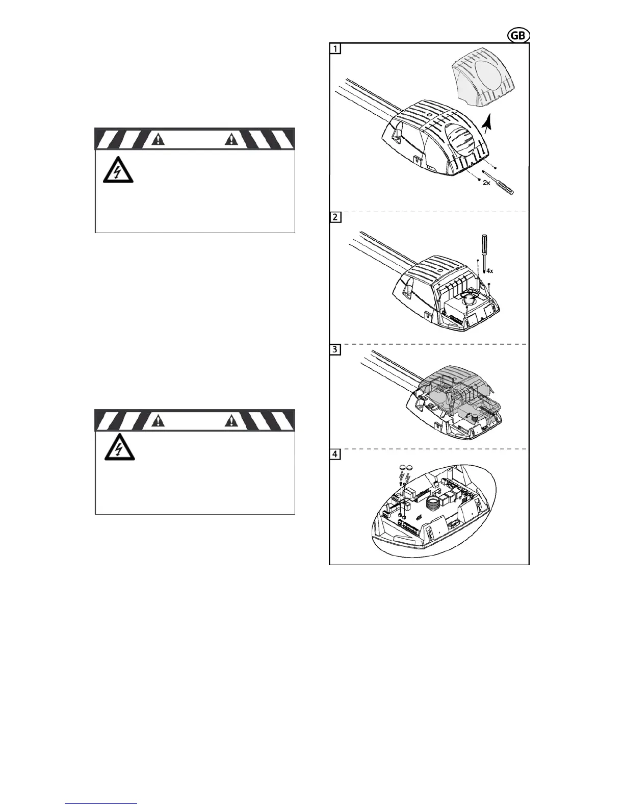
3.6.1 Insert red/green light module
If you want to insert the red/green light module,
you have to do the following steps:
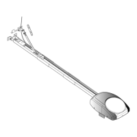
At first, the 2 safety screws have to be re-
moved as shown in Fig. 24.1 and the light
screws of
cover has to be taken off.
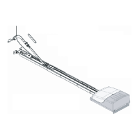
Then turn out the light bulb and the 4
the cover (Fig. 24.2).
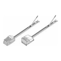
Now the cover can be taken off (Fig. 24.3) and
the red/green light module can be inserted
(correct position see Fig. 25 circuit board lay-
out).
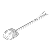
The red/green light module has to be attached
with the provided screws on the circuit board,
and the heads of the screws have to be iso-
lated with the provided plastic covers (Fig.
24.4).
Then break out the pre-punched notch for the
red/green light module in the cover and reas-
semble the cover – screws – light bulb and
ght cover. Now plli ug the opener to the mains.
Abb. 24.1-24.4
CAUTION
Before removing the
light cover - disconnect the
power plug! 230V ~
CAUTION
The heads of the
screws must be isolated with the
ti
unde
plas c covers. The screws are
r 230 V mains voltage!
 Loading...