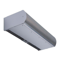
FIGURE 7 - Electrical Connections
5
For BACnet-IP Integration –
see Appendix D, “BACnet-IP integration.”
NOTE: The air curtain must have been ordered from
the factory with the Berner AIR to use this option.
For Serial Network Connection –
see Appendix A, “Serial Network Connection.”
NOTE: The air curtain must have been ordered from
the factory with this option.
For Remote Mounted Display Faceplate – If operation of
the Intelliswitch™ is to be through a Factory Ordered Remote
Mounted Display Faceplate, see Appendix B, “Remote Mounted
Display Faceplate.”
For Electric, Steam and Hot Water air curtains proceed to
Section VI - Field Connections otherwise proceed to
Section VII - Operation Instructions
VI. FIELD CONNECTIONS
A. ELECTRICALLY HEATED MODELS
The heater circuit may be controlled by a remote
thermostat or manually through the Intelliswitch™ located
on the discharge side of the air curtain. Overheating
protection is provided by auto reset thermal
cutouts built into the heater coil assembly
(see the wiring diagram).
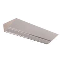
B. STEAM OR HOT WATER HEATED MODELS
Piping should be done in accordance with local
codes, regulations and standard practices.
Connect the building system supply and return to
the ¾” MPT nipples on the heating coil. See Figure 8.
FIGURE 8 - Steam/Hot Water Connections
 Loading...