INSTALLATION MANUAL
1) FOREWORD
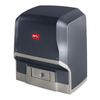
The ARES actuator is highly versatile in terms of installation options due to the
extremely low position of the pinion, the actuator’s compact nature and the
height and depth adjustment features it oers. The adjustable electronic torque
limiter provides anti-crush safety. Manual emergency operation is extremely easy
to perform using just a knob.
Stopping at end of travel is controlled by electromechanical microswitches.
The built-in control panel controls the start relays and safety devices (photocells,
safety edge) each time before performing any operation.
2) TECHNICAL SPECIFICATIONS
MOTOR
Power supply single-phase 230V ±10%, 50Hz (*)
Power input
400 W (ARES 1500)
240 W (ARES 1000)
Pinion module
4mm (18 teeth) (ARES 1500/ARES 1000)
4mm (25 teeth) (ARES 1500V / ARES 1000 V)
Leaf speed
9 m/min (ARES 1500/ARES 1000)
12 m/min (ARES 1500V / ARES 1000V)
Max. leaf weight
1500 Kg (ARES 1500) 1000 Kg (ARES 1000)
750 Kg (ARES 1500V) 500 Kg (ARES 1000V)
Max. torque
35 Nm (ARES 1500)
30 Nm (ARES 1000)
Impact reaction Electronic torque limiter
Lubrication Lifetime greased
Manual operation Knob-operated mechanical release
Type of use intensive
Buffer batteries (optional
extras)
Two 12V 1.2Ah batteries
Environmental conditions from -15°C to +60°C
Protection rating IP24
Noise level <70dBA
Operator weight 7 kg
Dimensions See Fig. K
CONTROL UNIT
Accessories power supply 24V ~ (180 mA)
Fuses Fig. G
Built-in Rolling-Code radio-receiver
frequency 433.92MHz
Setting of parameters and
options
Universal handheld programmer/LCD display
N° of combinations 4 billion
Max. n° of remotes that can
be memorized
63
(*) Special supply voltages to order.
Usable transmitter versions:
All ROLLING CODE transmitters compatible with
3) TUBE ARRANGEMENT Fig.A
Install the electrical system referring to the standards in force for electrical
systems CEI 64-8, IEC 364, harmonization document HD 384 and other national
standards.
4) PREPARATION FOR MOTOR MOUNTING FIG.B
• Makeaholeinthegroundtoaccommodatetheconcretepad,withanchors
embedded in the base plate for fastening the gearbox assembly, keeping to
the distances featured in FIG.B.
• Tokeepthebase plate in the right position during installation, itmaybe
useful to weld two iron plates under the track to which the anchors can then
be welded (FIG.M).
5) MOUNTING THE MOTOR FIG.C
6) MOUNTING DRIVE ACCESSORIES FIG.D-D1
7) RACK CENTRING WITH RESPECT TO PINION FIG.N-O1-P
DANGER - Welding must be performed by a competent person issued
with the necessary personal protective equipment as prescribed by
the safety rules in force FIG.O.
8) FASTENING LIMIT SWITCH BRACKETS FIG.E
9) STOPS FIG.Q
DANGER - The gate must be tted with mechanical stops to halt its
travel both when opening and closing, thus preventing the gate from
coming o the top guide. Said stops must be fastened rmly to the ground,
a few centimetres beyond the electric stop point.
10) MANUAL RELEASE (See USER GUIDE -FIG.2-).
Warning Do not JERK the gate open and closed, instead push it GENTLY to
the end of its travel.
----------------------------------------------------------
11) TERMINAL BOARD WIRING Fig. F-G
Once suitable electric cables have been run through the raceways and the auto-
mated device’s various components have been fastened at the predetermined
points, the next step is to connect them as directed and illustrated in the diagrams
contained in the relevant instruction manuals. Connect the live, neutral and earth
wire (compulsory). The mains cable must be clamped in the relevant cable gland
(FIG.R-ref.P1), and the accessories’ wires in the cable gland (FIG.R-ref.P2), while
the earth wire with the yellow/green-coloured sheath must be connected in the
relevant terminal (FIG.R-ref.S).
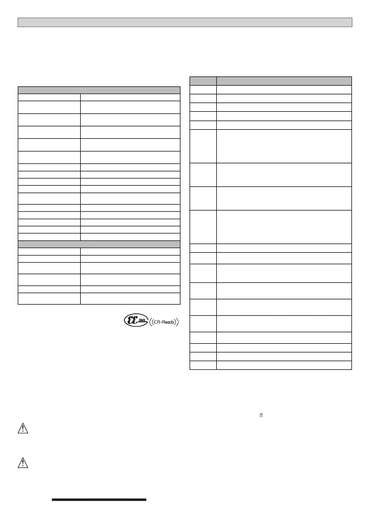
TERMINAL
DESCRIPTION
1-2 Motor connection.
3-4 24V transformer secondary windin (3-, 4+).
5-6 Closing limit switch SWC (5 Black common - 6 Red).
5-7 Opening limit switch SWO (5 Black common -7 Brown).
8-9 Flashing light 24V max. 25W.
10-11
Antenna (10 signal - 11 braiding).
Use an antenna tuned to 433MHz.
Use RG58 coax cable to connect the Antenna and Receiver.
Metal bodies close to the antenna can interfere with radio recep-
tion. If the transmitter’s range is limited, move the antenna to a
more suitable position.
12-13
Accessories power supply:
24 V operation with mains power on.
24 V (12-,13+) operation with no mains power and optional
buer battery kit.
14-15
Free contact (NO).
Gate Open Light SCA (24V max. 3W) or 2nd radio channel output
(FIG.G-ref.1).
This option can be set via the “logic menu”.
16-17
Safety device power supply output (photocell transmitter and
safety edge transmitter).
N.B.: output active only during operating cycle.
24 V Vsafe operation with mains power on.
24 V (16 -,17+) Vsafe operation with no mains power and optional
buer battery kit.
18 Safety device test input FAULT - PHOT (N.O.).
19-20
PEDESTRIAN control button (N.O.)
Opens the gate by the distance set with the “Partial Opening” parameter
21-22
START/CLOSE control button (N.O.). This option can be set via
the “logic menu”. Start - operation according to 3/4-step logic
Close - The command causes the leaf to close.
21-23
STOP input (N.C.)
The command stops movement.
If not used, leave jumper inserted.
21-24
PHOTOCELL input (N.C.)
Operation according to photocell during opening logic.
If not used, leave jumper inserted.
21-25
Safety edge input BAR (NC).
The command reverses movement for 2 secs.
If not used, leave jumper inserted.
21-26
OPEN control button (N.O.).
Gate opened with this command.
27 Safety device test input FAULT - BAR
31-32 230V~ transformer primary winding.
33-34 Single-phase power supply 230V, 50-60Hz (33N - 34L).
12 SAFETY DEVICES
NOTE: ONLY USE RECEIVING SAFETY DEVICES WITH FREE CHANGEOVER
CONTACT.
12.1 TESTED DEVICES FIG. U
12.2 NONTESTED DEVICES FIG. H, U
13 CALLING UP MENUS: FIG. 1
13.1) PARAMETERS MENU PARA PARAMETERS TABLE “A”
13.2) LOGIC MENU LOGIC LOGIC TABLE “B”
13.3) RADIO MENU radio RADIO TABLE “C”
- IMPORTANT NOTE: THE FIRST TRANSMITTER MEMORIZED MUST BE
IDENTIFIED BY ATTACHING THE KEY LABEL (MASTER).
In the event of manual programming, the rst transmitter assigns the RECEIVER’S
KEY CODE: this code is required to subsequently clone the radio transmitters.
The Clonix built-in on-board receiver also has a number of important advanced
features:
• Cloningofmastertransmitter(rollingcodeorxedcode).
• Cloningtoreplacetransmittersalreadyenteredinreceiver.
• Transmitterdatabasemanagement.
• Receivercommunitymanagement.
To use these advanced features, refer to the universal handheld programmer’s
instructions and to the general receiver programming guide.
13.4 LANGUAGE MENU language
Used to set the programmer’s language on the display.
20 - ARES
D811692 00100_04
 Loading...