INSTALLATION MANUAL
Warning!! While the autoset function is running, the obstacle detection
function is not active. Consequently, the installer must monitor the
automated system’s movements and keep people and property out of range
of the automated system.
10.7) LIMIT SWITCH ADJUSTMENT MENU L.SW ADJ Fig . E
Limit switch adjustment procedure:
1) Go to L.SW ADJ and conrm with OK.
2) The display reads CLOSE. Use the UP and DOWN keys to move the door to the
closing limit switch position. Conrm with OK. The display reads PRG.
3) If prompted by the display, turn the adjustment ring: anticlockwise if the display
reads UP; clockwise if the display reads DOWN. Once you have reached the
correct position, the display reads OK. Conrm with the OK key. The display
reads PRG.
4) The display reads OPEN. Use the UP and DOWN keys to move the door to the
opening limit switch position. Conrm with OK. The display reads PRG.
If the display reads KO, it means adjustment was not successful.
This may be caused by:
- the ESC key being pressed before adjustment was completed
- stored travel being too short
11) SCS OPTIONAL MODULES
11.1) SERIAL CONNECTION VIA SCS1 CARD (Fig. O)
The VENERE D control panel’s special serial inputs and outputs (SCS1) make the
centralized connection of a number of automated devices possible. That way,
all the automated devices connected can be opened or closed with a single
command.
Connect all VENERE D control panels using twisted pair cabling only, proceeding
as shown in the diagram in Fig. O.
When using a telephone cable with more than one pair, it is essential to use wires
from the same pair.
The length of the telephone cable between one unit and the next must not
be greater than 250 m.
At this point, each VENERE D control panel needs to be congured appropriately,
starting by entering a MASTER control panel that will have control over all the
others, which therefore have to be set as SLAVE units (see logic menu).
Also set the Zone number (see parameters menu) in the range 0 to 127.
The zone number allows you to create groups of automated devices, each of which
answers to the Zone Master. Each zone can have only one Master: the Master of
zone 0 also controls the Slaves of the other zones.
11.2) Interface with WIEGAND systems via SCS-WIE module.
Refer to the SCS-WIE module’s instructions.
11.3) Expanding inputs and outputs via the SCS-IO optional module.
The SCS-IO optional module can be used to add 2 inputs and 2 outputs to the
VENERE-D board (Fig. D).
To activate the connection between SCS-IO and VENERE-D, you need to plug the
SCS-IO module into the relevant connector and then set the ZONE parameter
to 129.
At this point, the 2 boards are synchronized and the SCS-IO board’s inputs/outputs
are managed by the VENERE-D board.
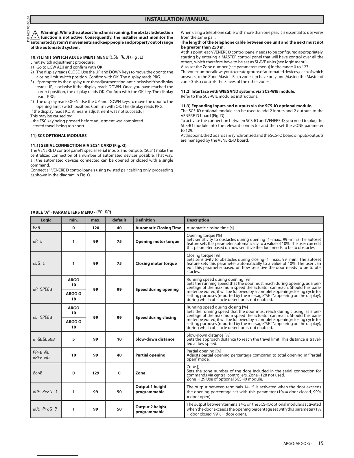
TABLE “A” PARAMETERS MENU - PARAM
Logic min. max. default Denition Description
tca
0 120 40 Automatic Closing Time Automatic closing time [s]
op. t
1 99 75 Opening motor torque
Opening torque [%]
Sets sensitivity to obstacles during opening (1=max., 99=min.) The autoset
feature sets this parameter automatically to a value of 10%. The user can edit
this parameter based on how sensitive the door needs to be to obstacles.
cls. t
1 99 75 Closing motor torque
Closing torque [%]
Sets sensitivity to obstacles during closing (1=max., 99=min.) The autoset
feature sets this parameter automatically to a value of 10%. The user can
edit this parameter based on how sensitive the door needs to be to ob-
stacles.
op speed
ARGO
10
99 99 Speed during opening
Running speed during opening [%]
Sets the running speed that the door must reach during opening, as a per-
centage of the maximum speed the actuator can reach. Should this para-
meter be edited, it will be followed by a complete opening/closing cycle for
setting purposes (reported by the message “SET” appearing on the display),
during which obstacle detection is not enabled.
ARGO G
18
cl speed
ARGO
10
99 99 Speed during closing
Running speed during closing [%]
Sets the running speed that the door must reach during closing, as a per-
centage of the maximum speed the actuator can reach. Should this para-
meter be edited, it will be followed by a complete opening/closing cycle for
setting purposes (reported by the message “SET” appearing on the display),
during which obstacle detection is not enabled.
ARGO G
18
dist.sloud
5 99 10 Slow-down distance
Slow-down distance [%]
Sets the approach distance to reach the travel limit. This distance is travel-
led at low speed.
partial
opening
10 99 40 Partial opening
Partial opening [%]
Adjusts partial opening percentage compared to total opening in “Partial
open” mode.
zone
0 129 0 Zone
Zone []
Sets the zone number of the door included in the serial connection for
commands via central controllers. Zona=128 not used.
Zone=129 Use of optional SCS -I0 module.
out prog 1
1 99 50
Output 1 height
programmable
The output between terminals 14-15 is activated when the door exceeds
the opening percentage set with this parameter (1% = door closed, 99%
= door open).
out prog 2
1 99 50
Output 2 height
programmable
The output between terminals 4-5 on the SCS-IO optional module is activated
when the door exceeds the opening percentage set with this parameter (1%
= door closed, 99% = door open).
ARGO-ARGO G - 15
D811627 00100_04
 Loading...