ST-120-38
5 SE-B2
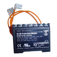
5.1 Monitoring functions SE-B2
The SE-B2 is used for semi-hermetic and open drive
screw compressors in combination with a time relay
and an electrolytic capacitor for oil flow monitoring (Sig-
nal Evaluation – Basic). It is intended for installation in
a switch cabinet.
• Fixation:
– can be fitted on a top hat rail.
Connecting the oil flow monitoring
Connect the SE-B2 in accordance with the schematic
wiring diagram, see chapter Schematic wiring dia-
grams, page 9.
NOTICE
Potential failure of the compressor protection
device and the motor due to improper connec-
tion and/or faulty operation!
The terminals M1-M2 or T1-T2 on the com-
pressor and B1-B2 on the protection device as
well as its two orange cables must not come
into contact with the control voltage or operating
voltage!
Determine the polarity (+ / -) of the orange instrument
leads of the SE-B2 using a voltmeter and connect the
electrolytic capacitor with correct polarity.
Technical data, see table 3, page 6.
Locked / reset
SE-B2 locked: The safety chain (11/14) is interrupted,
the lamp H1 is lit (signal contact 12) and indicates the
fault.
To reset, interrupt the voltage supply for at least 5
seconds. Let the compressor cool down and reset it
manually.
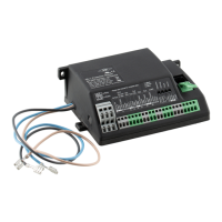
6 OFC
As an alternative to the SE-B2, the OFC can also mon-
itor the oil flow (Oil Flow Control). The time relay (K1T)
and electrolytic capacitor (C1) are not required for this.
The OFC is intended for installation in the switch cab-
inet.
The OFC locks after the interruption of the oil flow
switch (F7) and the end of the bridging time.
• Fixation:
– can be fixed with screws.
• Control delay:
– 15..20 s during start procedure
– 2..3s during operation
Connecting the oil flow monitoring
Connect the OFC in accordance with the schematic
wiring diagrams, see chapter Schematic wiring dia-
grams, page 9.
NOTICE
Potential failure of the OFC due to improper
connection and/or faulty operation!
Never apply any external voltage to the sensor
inputs T11 and T12 – not even for test pur-
poses!
Technical data, see table 3, page 6.
Locked / reset
OFC locked: The safety chain (M1/M2) is interrupted.
Display via signaling contacts A1/A2, lamp H1 is lit and
indicates the fault.
To reset, interrupt the voltage supply for at least 5
seconds. Let the compressor cool down and reset it
manually.
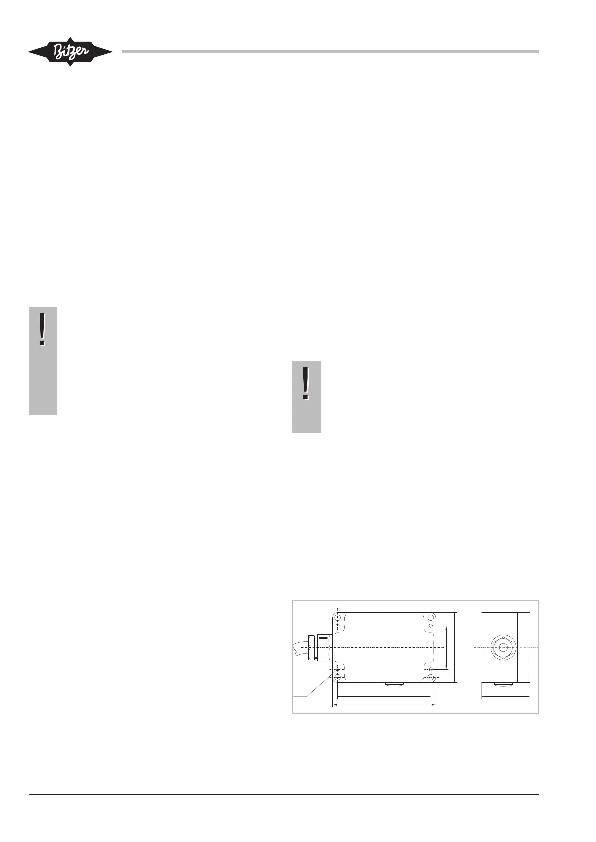
Dimensional drawing OFC
Fig.1: Dimensional drawing OFC
 Loading...