8
(Original instructions)
Labels on tool
The following pictograms are shown on the tool:
:
Warning! To reduce the risk of injury, the user must
read the instruction manual.
O
Wear safety glasses or goggles when operating this
tool.
N
Wear ear protection when operating this tool.
Electrical safety
#
This tool is double insulated; therefore no earth wire
is required. Always check that the power supply
corresponds to the voltage on the rating plate.
u If the supply cord is damaged, it must be replaced by the
manufacturer or an authorised Black & Decker Service
Centre in order to avoid a hazard.
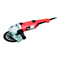
Features
This tool includes some or all of the following features.
1. On/off switch
2. Lock-off button
3. Side handle
5. Spindle lock
5. Guard
Assembly
Warning! Before assembly, make sure that the tool is
switched off and unplugged.
Fitting and removing the guard (g. A)
The tool is supplied with a guard intended for grinding
purposes only. If the unit is intended to perform cutting off
operations, a guard specic for this operation must be tted. A
suitable guard for cutting off operations part number 1004484-
03 is available and can be obtained from Black & Decker
service centres.
Fitting
u Place the tool on a table, with the spindle (6) facing up.
u Hold the guard (5) over the tool as shown.
u Align the holes in the adjusting plate (7) with the screw
holes (8).
u Press the guard down and insert the screws (9) into the
holes.
u Tighten the screws.
Removing
u Remove the screws (9).
u Remove the guard from the tool.
Warning! Never use the tool without the guard.
Adjusting the guard (g. B)
The guard can be rotated 180°.
u Slacken the screws (9) and the nut (10).
u Rotate the guard as required.
u Re-tighten the screws and the nut.
Fitting the side handle
u Screw the side handle (3) into one of the mounting holes
in the tool.
Warning! Always use the side handle.
Fitting and removing grinding or cutting discs (g.
C - F)
Always use the correct type of disc for your application.
Always use discs with the correct diameter and bore size (see
technical data). The maximum thickness for grinding discs is 6
mm, for cutting discs 3.5 mm.
Fitting
u Fit the guard as described above.
u Place the inner ange (11) onto the spindle (6) as shown
(g. C). Make sure that the ange is correctly located on
the at sides of the spindle.
u Place the disc (12) onto the spindle (6) as shown (g. D).
If the disc has a raised centre (13), make sure that the
raised centre faces the inner ange.
u Make sure that the disc locates correctly on the inner
ange.
u Place the outer ange (14) onto the spindle. When tting
a grinding disc, the raised centre on the outer ange must
face towards the disc (A in g. E). When tting a cutting
disc, the raised centre on the outer ange must face away
from the disc (B in g. E).
u Keep the spindle lock (4) depressed and tighten the outer
ange using the two-pin spanner (15) (g. F).
Removing
u Keep the spindle lock (4) depressed and loosen the outer
ange (14) using the two-pin spanner (15) (g. F).
u Remove the outer ange (14) and the disc (12).
Use
Warning! Let the tool work at its own pace. Do not overload.
u Carefully guide the cable in order to avoid accidentally
cutting it.
u Be prepared for a stream of sparks when the grinding or
cutting disc touches the workpiece.
u Always position the tool in such a way that the guard
provides optimum protection from the grinding or cutting
disc.
 Loading...