Vehicle Interface of Integrated Communication Optical Module (ICOM)
Page 14
User Guide
of 29
Copyright © BMW AG / ICOM User Guide
Version 1.0/ Februar 08
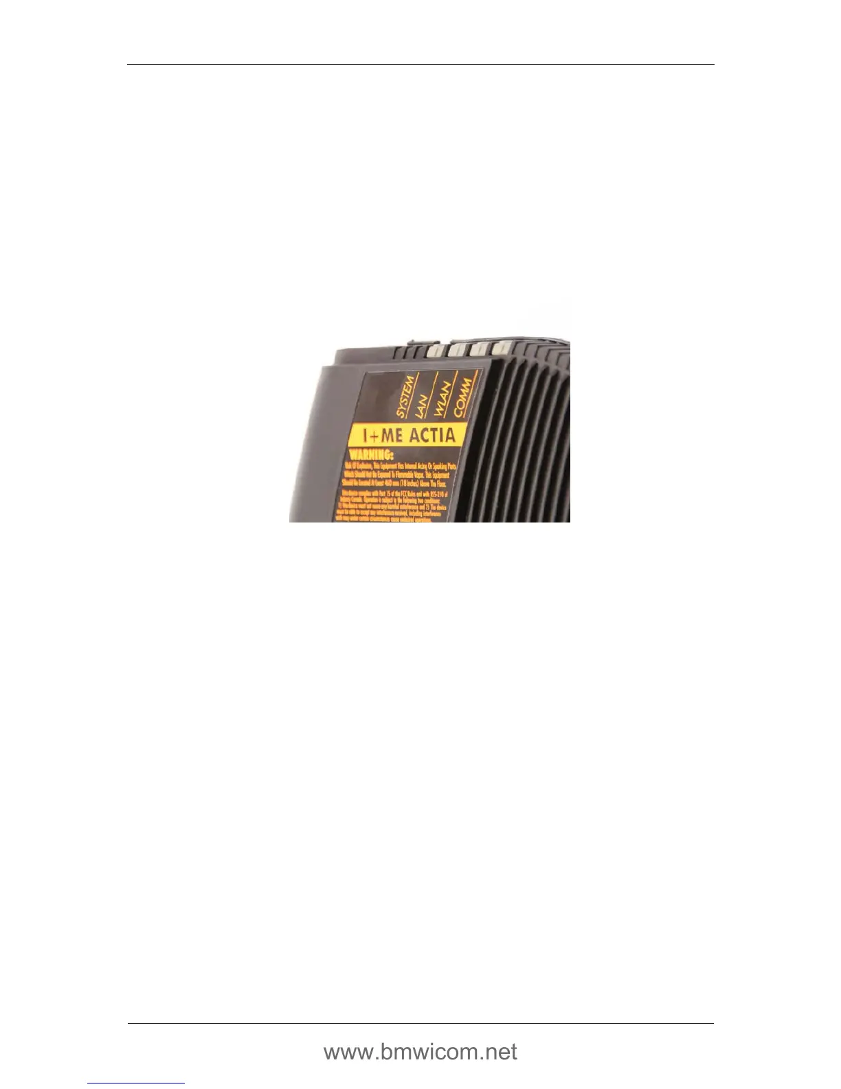
4.2.7. LEDs
For visualization of various device and communication states, four two-color (red and
green) LEDs are provided. A separate group of possible states and events has been
defined for each LED. There is a short description on the top of the housing beside each
LED; the name used already implies the meaning in each case. For special cases, all the
LEDs are combined to form a coded light pattern.
Fig. 7 LEDs on the top of the ICOM A device
General assignment:
• LED
SYSTEM
: display of the general device status
o green Operational
o flashing green ICOM A starting
o red Fault
o off ICOM A is not being supplied with voltage
• LED
LAN
: status of the cable-bound communication tester / Ethernet
o green Ethernet connection active (with data traffic
flashing)
o off Ethernet connection inactive
• LED
WLAN
: status of the radio communication tester / Ethernet via WLAN
o green Infrastructure (with traffic, flashing)
o yellow*
1
Ad-hoc (with traffic, flashing)
o off Without WLAN communication
• LED
COMM
: status of the communication via communication line, D-CAN or vehicle
Ethernet
Special cases:
• Running lights: all LEDs come on and go out in succession
o red Software update of the ICOM
*
1
yellow = the relevant LED lights up simultaneously red and green
 Loading...