Vehicle Interface of Integrated Communication Optical Module (ICOM)
Page 19
User Guide
of 29
Copyright © BMW AG / ICOM User Guide
Version 1.0/ Februar 08
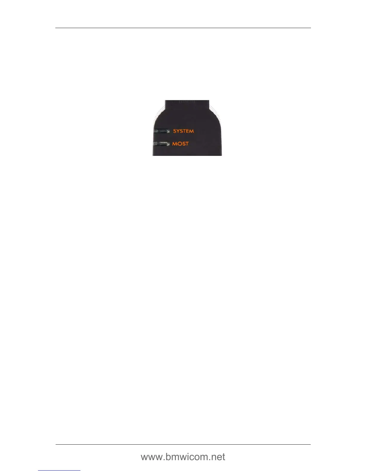
4.3.4. LEDs
For visualization of certain device and communication states, two two-color (red and green) LEDs
are provided. A separate group of possible states and events has been assigned to each LED.
Similarly to the ICOM A, short descriptions with names according to the relevant function can be
found on the top of the housing beside each LED.
Fig. 12 Light-emitting diodes on the ICOM B housing
The following light and flash codings are defined:
• LED
SYSTEM
: display of the general device status:
o Off Device is not being supplied with voltage
o yellow *
1
ICOM B is being initialized
o red Start / initialization problems
o green Device is operational
o flashing green Communication
• LED
MOST
: status of the MOST communication:
o Off No light on the MOST interface
o red Light that cannot be locked
o green Stable LOCK
o yellow *
1
Unstable LOCK
*
1
yellow = the relevant LED lights up simultaneously red and green