Front & Rear Panel Connection Diagrams
1 9
2
4 5 6 7 83
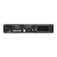
1. Console MIC - Used for intercom and emergency page functions. Normally
configured (via terminal link) as microphone 1. Provision has been made to option-
ally mute the monitor speaker when the MIC 1 switch is depressed.
2. Emergency Page - Red push button used to make announcements to all
speaker stations; overrides program distribution and room selector panel settings.
3. MIC 1, MIC 2, AUX - Push buttons used to select input source; choose from
MIC 1 (console or external microphone), MIC 2 (external microphone), or AUX,
as desired.
4. All Rooms - Push button used to distribute program to all speaker stations with
room selector panel switches set to the PROGRAM or OFF positions.
5. Press to Talk/Release to Listen - Push button used to communicate with
speaker station selected for intercom communication. Does not affect the distri-
bution of program material to other stations.
6. Program/Talk Level - LED Indicators: N (normal) lights green to indicate
proper signal level; P (peak) lights amber to indicate higher than normal signal
level; O (overload) lights red to indicate possible signal clip.
7. Program - Amber color knob used to adjust level of program material.
8. Monitor/Listen - Green color knob used to adjust volume level to front panel
speaker.
9. Front Panel Speaker - Used to monitor a program or to listen to a station
via the INTERCOM channel.
3
267 345
911 8
1
Front
Panel
Rear
Panel
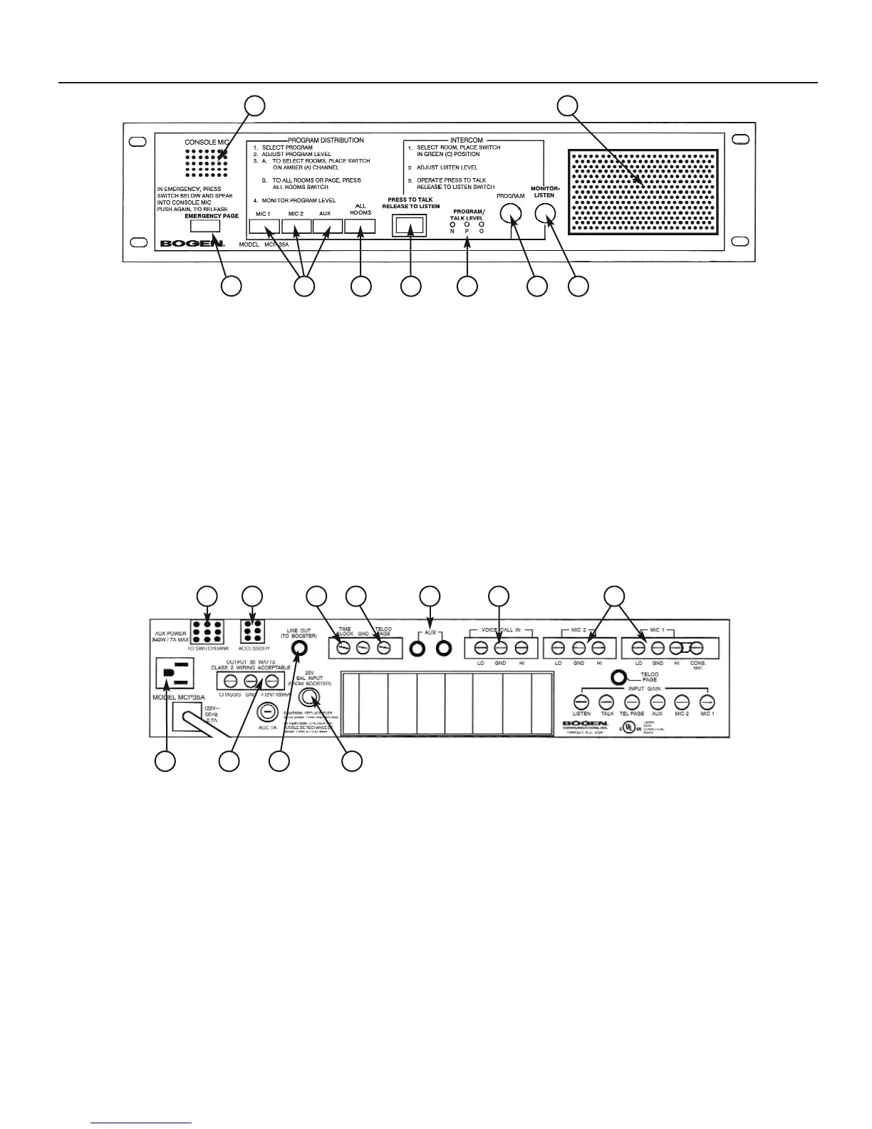
1. Microphone Inputs - A terminal strip provides connection for two-low im-
pedance balanced microphones. May (optionally) provide phantom power. The
console microphone is used as MIC 1; however, this feature may be disabled. Use
two-conductor shielded microphone cable.
2. Voice Call-In - Connects parallel lines from station call-in switches with a
two- conductor shielded cable.
3. AUX - Two phono jacks accept an unbalanced line-level input from CD player,
tuner, etc.
4. Telco Page - Shorting the TELCO PAGE terminal to ground activates the
Telco page feature. The associated TELCO PAGE jack accepts an unbalanced
line input from Model WMT1A telephone interface device. This input has priority
over all other system functions except for the front-panel-mounted EMERGENCY
PAGE.
5. Time Clock - Shorting the TIME CLOCK Terminal to ground provides single-
circuit time signal capability.
6. Accessory - Mounting port for optional connector used to interface the Model
MCPB Control Panel.
7. Switch Bank - 9-pin connector accepts three audio pairs and three control
wires from room selector panels.
8. 25V BAL. INPUT - (From Booster) Stereo phone jack accepts input from a
booster amplifier. Refer to Figure 6.
9. LINE OUT - Unbalanced line-level output to recorder or booster amplifier. The
output level is adjustable with the front panel LEVEL control.
10. 12V DC & GND Terminals - For powering SCR25A and other accessories.
11. AUX Power - 840-watt, three-wire auxiliary power receptacle for accessory
equipment.
10
 Loading...