4
Power and Grounding
The MCP35A Master Control Panel operates from a 120 volt, 60Hz AC
source and consumes approximately 100 watts. The AC line cord is ter-
minated in a thee-prong plug, and should be plugged into a three-wire
grounded outlet providing nominal 120 volts, 60 Hz AC. It is important that
the control panel be grounded properly.
Auxiliary Power Receptacle
An 840-watt, three-wire grounded outlet is provided on the rear panel to
supply power to accessory equipment. Auxiliary equipment connected to
this outlet will be grounded, provided the MCP35A line cord has been prop-
erly grounded.
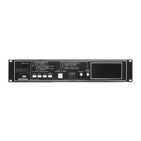
Line-Matching Transformers
The MCP35A Master Control Panel is designed for 25-volt constant-voltage
distribution systems. All system loudspeakers must be provided with line-
matching transformers. See Figure 1.
Caution
:
Speakers and transformers must be properly matched with
respect to power requirements. The internal 35-watt amplifier of the MCP35A
should not be connected to a load of more than 75 loudspeakers, each
tapped at ½ watt (approx. 18 ohm). If a BPA60 booster amplifier is used,
the load should not exceed 125 loudspeakers, each tapped at ½ watt
(approx. 10 ohm). If loudspeakers are tapped at greater than ½ watt, either
the total number of loudspeakers must be reduced, or a more powerful
amplifier used.
Caution
:
To avoid electric shock, be sure to disconnect AC Power Cord
before removing the cover of the amplifier unit.
Warning
:
DO NOT perform any function requiring the removal of the
cover of the unit unless you are qualified to do so.
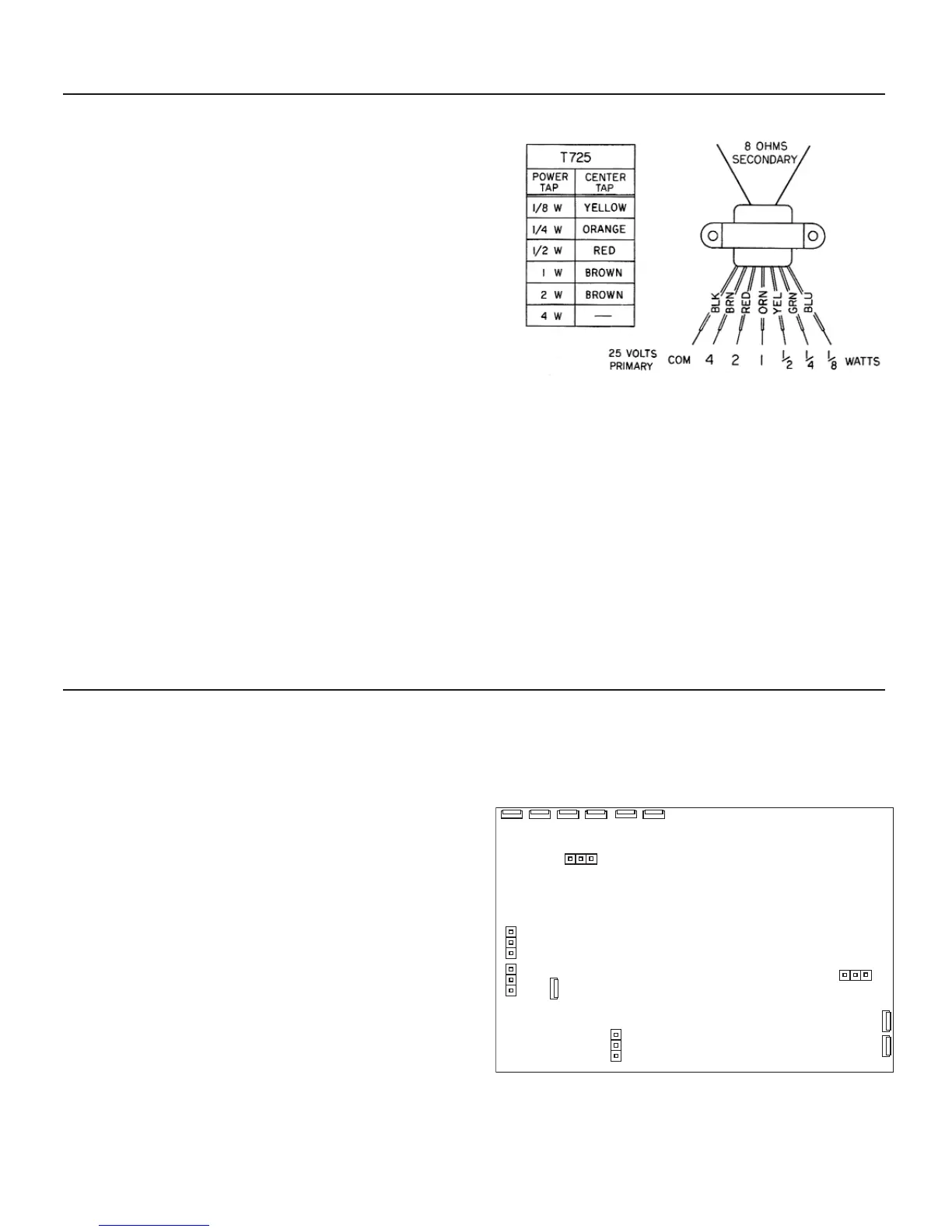
Gain Adjustments
(Internal)
Internal controls are provided to set the level of emergency page volume,
privacy tone volume, and time tone volume. These controls are factory
set; under normal circumstances no further adjustment is required.
Schematic/Circuit board designations: Emergency Page Volume, R39;
Supervisory Tone Volume, R74; Time Tone Volume, R75.
Phantom Power
(Internal)
Phantom power may be supplied to MIC 1 and MIC 2 inputs to permit use
of phantom-powered condenser microphones. To enable, move shunts J1
(for MIC 1) and J2 (for MIC 2) to the ON position.
TELCO Page/MIC 2
(Internal)
Shunt J3 selects the TELCO PAGE input jack or the MIC 2 input terminals
for the telephone page function. Place the shunt at the MIC 2 position
when using the MIC 2 terminals for telephone paging applications.
Supervisory Tone Defeat
(Internal)
Shunt J5 enables/disables the supervisory tone feature. Move the shunt
to the OFF position to disable the supervisory tone.
Installation
Adjustments / Modifications
Figure 1 – Model T725 Transformer
Figure 2 – Jumper Locations on MCP35A Card
 Loading...