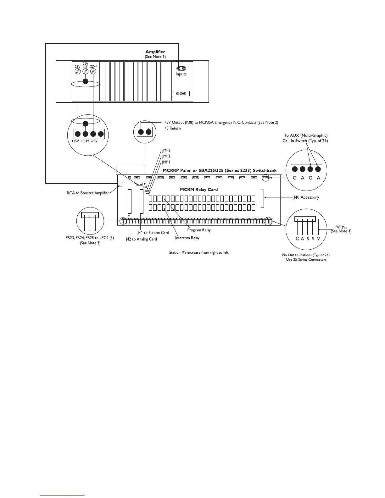
Note 1: When an external booster amplifier is used, remove jumpers JMP2 & JMP3. Each Relay Module must use
a separate booster amplifier.
Note 2: If using this option with one MCRM module, connect P28 “output” and “return” to MCP35A N.C. contacts
and remove JMP1. If this option is used with multiple relay modules, parallel the “output” and “return” wires
on P28 to each relay module and remove JMP1 on each module.
Note 3: Only the first 24 stations and PR23 & PR24 can be used by the Multicom 2000.
Note 4: The “V” pin is provided for special applications and is not used in typical station installations ("V" pin
is omitted on Rev B versions and higher). It is only on the first station and is furthermost to the right.
DO NOT connect any station to this pin.
Figure 12 - Relay Modules
 Loading...