27
Telephone Station
Telephone Access Card (Model MCTCA)
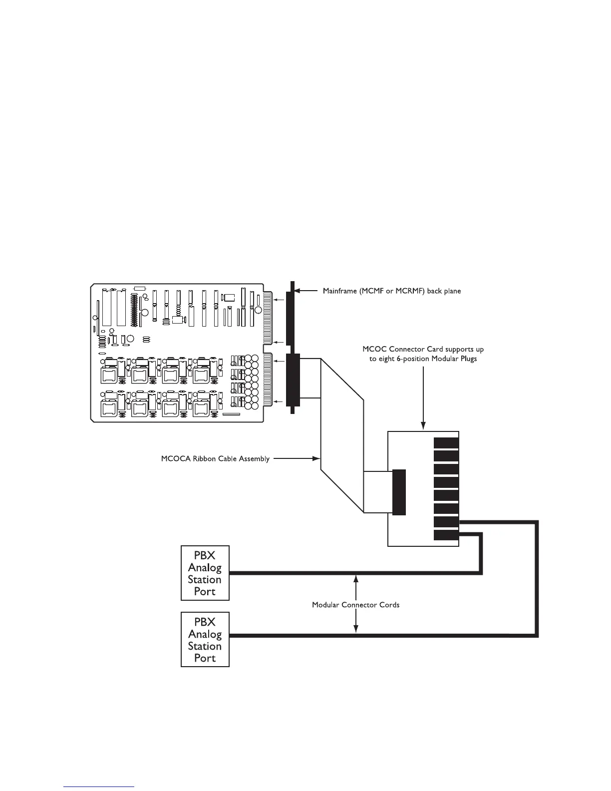
The Telephone access option consists of the Model MCTCA circuit card. Model MCOC connector card and MCOCA
ribbon cable assembly. Fuses F1, F3, F5, F7, F9, F11, F13 and F15 are Pico fuses, 250mA. F17 is 1A Slo-Blo Pigtail.
In wall-mounting systems, the MCTCA is usually installed in slot #11 of the MCMF Mainframe (reduces system
capacity).
In rack-mounted systems with one card cage (MCRMF), the MCTCA installs in slot #12. In rack-mounted systems
with two card cages, a second MCTCA can be installed in slot #12 of the second card cage to provide additional
external telephone capacity.
The MCOC card contains eight 6-position modular telephone jacks which can be connected to station ports of a
PBX system (the two center conductors are Tip & Ring).
Figure 25 - MCTCA Connection
 Loading...