20
Station Equipment Installation
The following is a list of staff station equipment that can be connected to the Multicom 2000.
MCDS4 Administrative Telephone (DTMF dialing with 4-line x 16-character LCD display panel)
MCESS DTMF Dialing, Enhanced Staff Telephone, Desk Mount
MCWESS DTMF Dialing, Enhanced Staff Telephone, Wall-Mounted
CA15C Call-In Switch (Press to Call)
CA21B Call-In Switch (Press to Call/Privacy)
In addition to the telephone/handset at each location, the system is designed so that there can be a ceiling- or wall-
mounted speaker at each location for the purpose of intercom communication, paging, program material distribution,
and dissemination of time signals and alarm tones.
We recommend the Bogen S86 loudspeaker equipped with the T725 line matching transformer as the speaker of
choice at each station location. This speaker is available mounted to a ceiling grille or enclosed in a wall-mounting
baffle. Figures 17- 21 show wiring diagrams for connection to each type of staff station equipment. In these illustrations,
the transformer is tapped at 1/2 watt. The transformer may be tapped at any desired power level; however,
1/2-watt is the recommended load for each speaker. In any event, make sure that the total load to relay card or
relay module (group of 24 stations) does not exceed 20 watts. Contact our Applications Engineering Department if
the load on a card must exceed 20 watts.
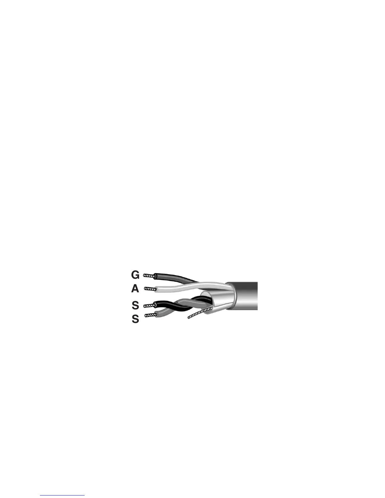
Figure 7 shows the termination of one station’s cable at the relay card or relay module.
Important: Termination of staff station wiring at the control center must be made using Bogen 25-Series
connector kits to maintain warranty coverage.
Attach the conductors to the connector as shown in Figure 7, using the TL156 tool. The connector is then placed
on the corresponding pins on the relay card or relay module.
Figure 7 - Termination of one pair shielded and one unshielded pair to centerline connectors
 Loading...