14 | English
1 609 92A 0NE | (3.6.14) Bosch Power Tools
Noise/Vibration Information
Sound emission values determined according to
EN 60745-2-1.
Typically the A-weighted noise levels of the product are:
Sound pressure level 96 dB(A); Sound power level
107 dB(A). Uncertainty K =3 dB.
Wear hearing protection!
Vibration total values a
h
(triax vector sum) and uncertainty K
determined according to EN 60745:
Drilling into metal: a
h
=5.5m/s
2
, K=1.5 m/s
2
,
Impact drilling into concrete: a
h
=15m/s
2
, K=2.4 m/s
2
,
Screwdriving without impact: a
h
<2.5m/s
2
, K=1.5 m/s
2
,
Tapping: a
h
<2.5m/s
2
, K=1.5 m/s
2
.
The vibration level given in this information sheet has been
measured in accordance with a standardised test given in
EN 60745 and may be used to compare one tool with anoth-
er. It may be used for a preliminary assessment of exposure.
The declared vibration emission level represents the main ap-
plications of the tool. However if the tool is used for different
applications, with different accessories or insertion tools or is
poorly maintained, the vibration emission may differ. This
may significantly increase the exposure level over the total
working period.
An estimation of the level of exposure to vibration should also
take into account the times when the tool is switched off or
when it is running but not actually doing the job. This may sig-
nificantly reduce the exposure level over the total working
period.
Identify additional safety measures to protect the operator
from the effects of vibration such as: maintain the tool and the
accessories, keep the hands warm, organisation of work pat-
terns.
Declaration of Conformity
We declare under our sole responsibility that the product de-
scribed under “Technical Data” is in conformity with all rele-
vant provisions of the directives 2011/65/EU, 2014/30/EU,
2006/42/EC including their amendments and complies with
the following standards: EN 60745-1, EN 60745-2-1.
Technical file (2006/42/EC) at:
Robert Bosch GmbH, PT/ETM9,
70764 Leinfelden-Echterdingen, GERMANY
Robert Bosch GmbH, Power Tools Division
70764 Leinfelden-Echterdingen, GERMANY
25.03.2014
Assembly
Before any work on the machine itself, pull the mains
plug.
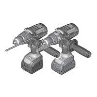
Auxiliary Handle (see figure A)
Operate your machine only with the auxiliary handle 7.
The auxiliary handle 7 can be set to any position for a secure
and low-fatigue working posture.
Turn the bottom part of the auxiliary handle 7 in counterclock-
wise direction and swivel the auxiliary handle 7 to the desired
position. Then retighten the bottom part of the auxiliary han-
dle 7 by turning in clockwise direction.
Adjusting the Drilling Depth (see figureA)
The required drilling depth X can be set with the depth stop 8.
Turn the bottom part of the auxiliary handle 7 in anticlockwise
direction and insert the depth stop 8.
Pull out the depth stop until the distance between the tip of
the drill bit and the tip of the depth stop corresponds with the
desired drilling depth X.
Afterwards, tighten the bottom part of the auxiliary handle 7
again by turning in clockwise direction.
The knurled surface of the depth stop 8 must face upward.
Changing the Tool
Wear protective gloves when changing the tool. The
drill chuck can become very hot during longer work peri-
ods.
Keyless Chuck (see figure B)
The drill spindle is locked when the On/Off switch 5 is not
pressed. This makes quick, convenient and easy changing of
the tool in the drill chuck possible.
Open the keyless chuck 1 by turning in rotation direction ,
until the tool can be inserted. Insert the tool.
Firmly tighten the collar of the keyless chuck 1 by hand in ro-
tation direction until the locking action (“click”) is no longer
heard. This automatically locks the chuck.
The locking is released again to remove the tool when the col-
lar is turned in the opposite direction.
Key Type Drill Chuck (see figure C)
Open the key type drill chuck 10 by turning until the tool can
be inserted. Insert the tool.
Insert the chuck key 9 into the corresponding holes of the key
type drill chuck 10 and clamp the tool uniformly.
Screwdriver Tools (see figure D)
When working with screwdriver bits 11, a universal bit holder
12 should always be used. Use only screwdriver bits that fit
the screw head.
For driving screws, always position the “Drilling/Impact Drill-
ing” selector switch 2 to the “Drilling” symbol.
Replacing the Drill Chuck
Before any work on the machine itself, pull the mains
plug.
For power tools without spindle lock, the drill chuck
must be replaced by an authorised after-sales service
agent for Bosch power tools.
Henk Becker
Executive Vice President
Engineering
Helmut Heinzelmann
Head of Product Certification
PT/ETM9
OBJ_BUCH-806-003.book Page 14 Tuesday, June 3, 2014 9:44 AM
 Loading...