| 39
Installation Instructions
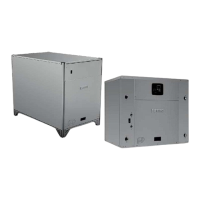
Bosch IDS BOVA15 Split System Heat Pump - BTC 761701317 A (02.2022)
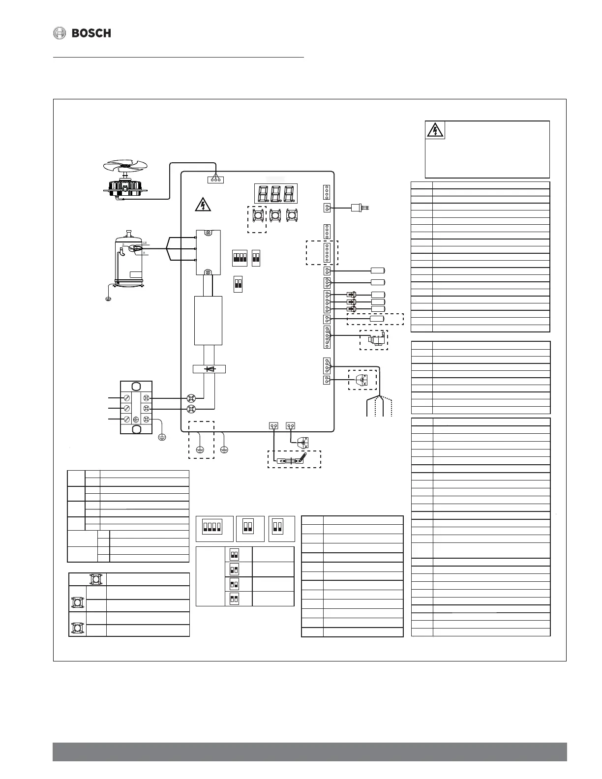
16 Wiring Diagram
16.1 BOVA24/36-15 (2/3 Ton)
Figure 60
SW4
1 2 3 4
ON
SW5
1 2
ON
SW1
FORCE
CN10
CN25
CN21
CN7
CN20
CN13
HPS
T5
PT
T3
T4
T3L
Th/T6
RV
EEV
CN14
CN16
CN9
CN12
PEV
CN17
DSP1
IPM
Main Board
GR/W
BR/V
BK/U
CN32
FAN
CN1 L1
CN2 L2
Y/G
Y/G
Power in
Terminal block
CCH
CN8
FORCE
PRESS
6s
PRESS
1s
SS
ERPSSERP
s1s1
PRESS
6s
CHECK
Detailed
reference manual instructions
SW3
Wifi setting(reserve)
YELLOW
WHITE
BLUE
C B Y W
To thermostat
USE COPPER
CONDUCTORS ONLY
Check the system parameters
Test mode(Not used)
Forced cooling/heating
(Charge mode)
PFC
Forced defrosting
V2 U2
BROWN
BLACK
WHITE
BLUE
Note:
1.B terminal to be connected with
themostat(O/B) wiring heat pump
heating operating,energized for heating.
2.EEV、RV for HP system.
3.B、W signal for HP system.
ORANGE
RED
BK
*
6:
21
ON
OFF
*The factory Default
*
21
6:
ON
OFF
SW5-1
Enter defrost
SW5-2
Quit defrost
OFF
ON
OFF
ON
Normal
SW4-2
SW4-3
SW4-4
OFF
ON
SW4-1
Normal
ON
OFF
*
*
*
*
*
OFF
ON
OFF
ON
Unused
For 48K model
For 60K model
Must be set at OFF position
Unused
Must be set at OFF position
Adaptive capacity output disable
Adaptive capacity output enable
Normally cooling/heating
Accelerated cooling/heating
Operating time is reduce 10%
Defrosting extended for 60 seconds
CN11
*
W2
SW6
1 2
ON
SW2
CHECK
SW3
6:
21
ON
OFF
For 24K model
For 36K model
21
ON
OFF
21
ON
OFF
21
ON
OFF
21
ON
OFF
Set capacity
Y/G
GND1 GND2
COMP.
L1
L2
Mumber Point check content
0
Outdoor unit capacity,example:H3=Heat pump 3 ton
1 Outdoor unit mode:0-standby,2-cooling,3-heating
2 Outdoor unit set compressor speed(Hz)
3 T3:outdoor coil temp.(°F)
4 T4:outdoor ambient temp.(°F)
5 T5:compressor discharge temp.(°F)
6 Reserve
7 T3L:(liquid line temp.)(°F)
8 Tf:module temp.(°F)
9 Pe:evaporating pressure(PSI)
10 Pc:condensing pressure(PSI)
11
Tes target evaporating temp.(only for cooling mode)(°F)
12 Te:evaporating temp.(°F)
13 Tcs target condensing temp(only for heating mode)(°F)
14 Tc:condensing temp.(°F)
15
Target of the compressor discharge superheat
(heating mode only):Target value (°F)
16 Compressor diacharge superheat(°F)
17 Opening of EEV
18 Outdoor fan speed
19 Compressor current(A)
20 Power AC voltage Input(V)
21 Compressor input dc voltage (V)
22 Continuous running time of the compressor(min)
23 Last fault code
24 Software version
25 Remark"--"
HPS
High pressure switch
T5 Comp. discharge temp. sensor
PT Pressure transducer
T3 Condensor temp. sensor
T4 Ambient temp. sensor
T3L Condensor outlet temp. sensor
Th/T6
Comp. return temp. sensor
EEV Electric expansive valve
RV Reversing valve
PEV Pressure equalizer valve
CCH Crankcase heater
COMP. Compressor
TEMP. Temprature
CODE
CODE
Fault description
Description
E4 Temprature sensor fault (T3,T4,T5,T3L,TF)
F1 High pressure switch fault (HPS)
H8 Pressure transducer fault (PT)
E6 DC fan motor fault
P8 DC fan motor hurricane/typhoon protection
E5 High/Low voltage protection
E9 EEPROM fault
H0 Communication fault in main control chip
L0-L9 The IPM module protection(only for analysis)
C3 The coil sensor is seated fault in cooling(T3)
E7 Compressor discharge sensor is seated fault (T5)
PH Low discharge superheat protection
P1 High pressure(HPS) protection
P5
Condensor coil temperature protection in cooling (T3)
P4 High T5 protection
P0 HighControl board temperature protection (TF)
P3 Compressor over current protection
P2 Low pressure protection in cooling or heating (PT)
H5 5 times (P2) protection in 100 minutes, lockup
AtL Ambient Temperature Limited T4 (heat pump)
┣
Forced operation mode
L Running indication under T3 limited condition
D Running indication under T5 limited condition
P Compression ratio protection limit
F Running indication under TF limited condition
C
Running indication under current limited condition
U
Running indication under low voltage limited condition
A Running indication under return oil model
dF Running indication under defrost model
U
V
W
Y/G
5
.
WARNING
FAILURE TO FOLLOW THIS WARNING COULD RESULT
IN PERSONAL INJURY OR DEATH
ELECTRIC HAZARD 380 VOLTS DC
WAIT 3 MINUTES AFTER DISCONNECTING POWER,THEN
VERIFY DC VOLTAGE LESS THAN 42 VDC AT INVERTER
TEST POINTS P-N. COMPONENTS MAY STORE A
DANGEROUS ELECTRICAL POTENTIAL OF 380 VOLTS DC.
SW6
 Loading...