English | 37
Bosch Power Tools F 016 L81 115 | (7.10.14)
Lawn Preparation
Remove stones, loose pieces of wood, wire, live mains cables
and other foreign objects from the cutting area.
Make sure that the cutting area is even and has no ditches,
grooves and steep slopes above 20° that are clear obstruc-
tions for the machine.
Cut the main area of the lawn with a conventional mower to a
max. height of 40 mm and the perimeter wire area to a max.
height of 20 mm.
Installation
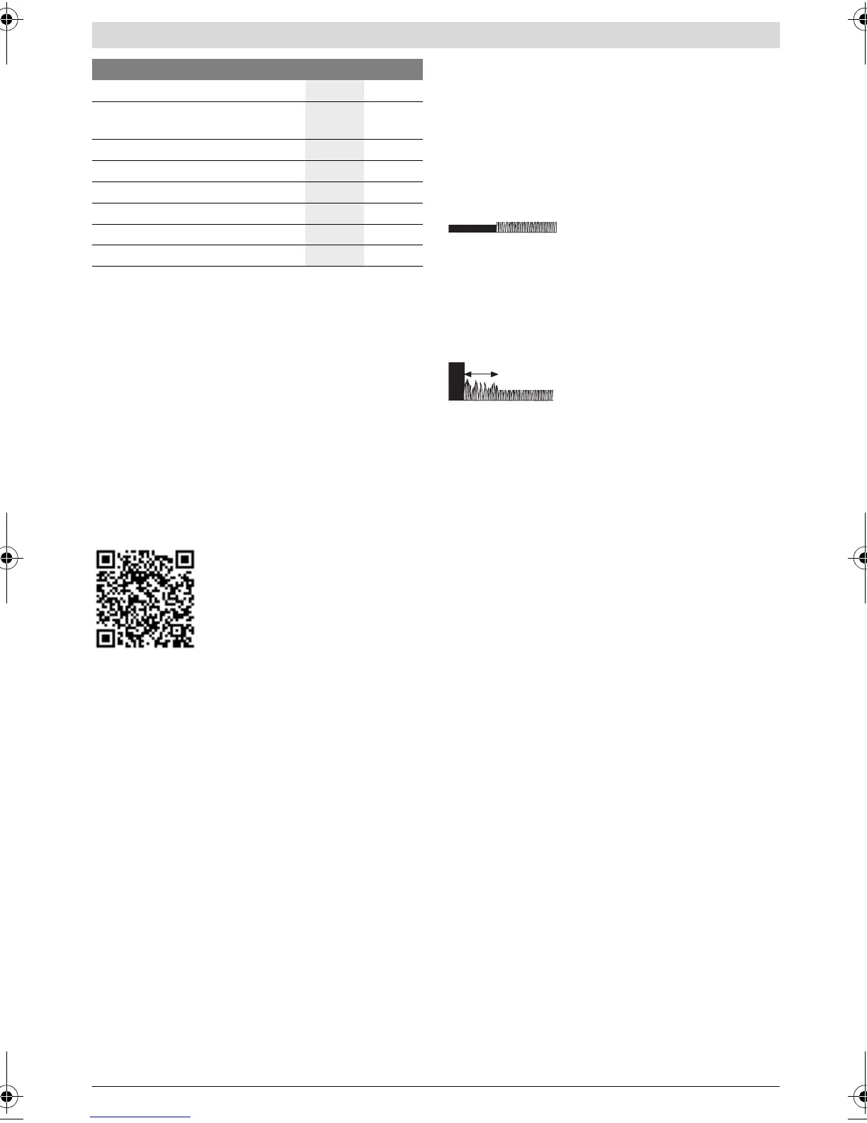
For a video guide on how to install the Indego please visit
www.bosch-indego.com or use the following QR-Code.
Select a position for the docking station, horizontally levelled
and out of direct sunlight.
Note: The docking station must be positioned on the wire at
an outer edge of the cutting area. It cannot be positioned by
the side of a shed or workshop that appears as an island with-
in the cutting area.
Make sure that the docking station is placed beside the cut-
ting area with a straight 1.5 m track in front of the docking sta-
tion and a straight 1 m track behind. Whilst stood in the grass
area to be cut it is important that the docking station charging
pins point to the left. (see figure 2)
Note: If the docking station is positioned with the charging
pins pointing either into the grass area or pointing to the right
the Indego will not run correctly.
Pull the wire end through the front hole of the base plate and
straight through the wire duct and the rear hole. Fix the wire
with a peg inline with the hole. Cut off insulation carefully and
connect the wire to the right hand (red) terminal. (see
figures 4– 5)
Fix the docking station with 4 supplied fixing pins to the
ground. (see figure 6)
Lay out the perimeter wire anti-clockwise and flush to the
ground. Observe the minimum distances from lawn edges,
steps, walls, ponds, etc. Use the spacing guide. (see figure 7)
Note: The cable should be positioned so that the Indego will
not be more than 16 m away at anytime.
If the working area borders against a flat path or surface that
is level with the lawn the Indego will be able to run over it. In
such cases the perimeter wire should be positioned right up
to the edge of the lawn.
Note: Perimeter wire can be buried up
to a maximum depth of 5 cm. It is recommended to mark out
permanent objects within the garden. This will prevent the In-
dego colliding with the object and reduce wear on the shell.
Objects on the lawn below 6 cm height e.g. trees, ponds, flow-
er beds etc. must be delimited in a clockwise direction. The
lines to and from these zones may not cross but the wire
should be touching. (see figure 7)
Note: Approximately 20 cm of lawn
around the fixed object and around the
edge of the lawn will not be mown.
Fix the wire with the first peg next to the docking station, ten-
sion and fix with pegs at a distance of approx. 50 cm. (see
figure 7)
Continue the loop and bring the wire to the back of the dock-
ing station and inline with the other end of the wire. Fix the
second end of the wire also with the peg. Perimeter wire and
peg should be installed inline. Shorten the wire, cut off insula-
tion carefully and connect the wire to the left hand (black) ter-
minal. (see figure 10)
Clip on the protective cover of the docking station. (see
figure 11)
Note: If extra perimeter wire is required this can be added us-
ing one connector. (see figure 8)
The wire can be extended up to the maximum allowed length
of 450 m.
Note: If verticutting or raking is intended avoid the perimeter
wire.
Install the power supply in a cool, dry environment. Connect it
with the docking station and an indoor mains socket. (see
figure 12)
Check the indicator on the docking station (see figure 13):
–Indicator lights up continuously green, if the output volt-
age of the power supply is available and the perimeter wire
is not interrupted.
–Indicator does not light up when the output voltage of the
power supply is not available.
Installing an additional lawn
(Indego 1300)
The Indego 1300 can be used in up to three different lawns.
To install an additional cutting area/lawn you will need to have
purchased an additional docking station (F 016 800 384/
F 016 800 438) and the required perimeter wire and pegs.
To install the additional area please follow the installation in-
structions from the beginning of this section.
Plug in isolator key
14 9
Charge battery by putting the machine
into docking station 15 10
Welcome screen = Refer to manual
16 10
Lift up and carry the machine
17 11
Set height of cut
18 11
Logicut Intelligent Cutting
19 12
Cleaning
A 13
Maintenance
B 13
Action Figure Page
OBJ_BUCH-1573-007.book Page 37 Tuesday, October 7, 2014 12:49 PM
 Loading...