Making the electrical connections | 47
6 720 810 590 (2015/05)
Greenstar FS
7.2.5 Connecting mains power supply
▶ Route the power cable (AC 120 V, 60 Hz) from the emergency
shutoff switch to the boiler.
▶ Insert cable into the junction box as shown in Fig. 49.
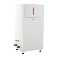
▶Connect cable to the white plug according to Fig. 48.
Fig. 48 Attach plug (mains power supply)
[1] L (120 VAC, 60 Hz)
[2] PE (GND, Ground)
[3] N (Neutral)
[4] White plug (in the junction box upon delivery)
▶ Connect white plugs and insert grommet until stop.
Fig. 49 Cable connected (mains power supply)
▶ Mount junction box on the rail.
7.2.6 Low voltage (LV) junction box
The low voltage installer junction box provides connections to sensors,
thermostat and programmers.
Bosch room controls
Connect only Bosch room controls to the internal BUS of this boiler.
For installation and electrical connection of Bosch controls, see
installation instructions for the Bosch control.
Connecting external manual reset high limit or low water cut off
(LWCO)
This connection allows the installation of external safety switches.
• External manual reset high limit
• Low water cut-off (LWCO)
• Radiant overheat protection
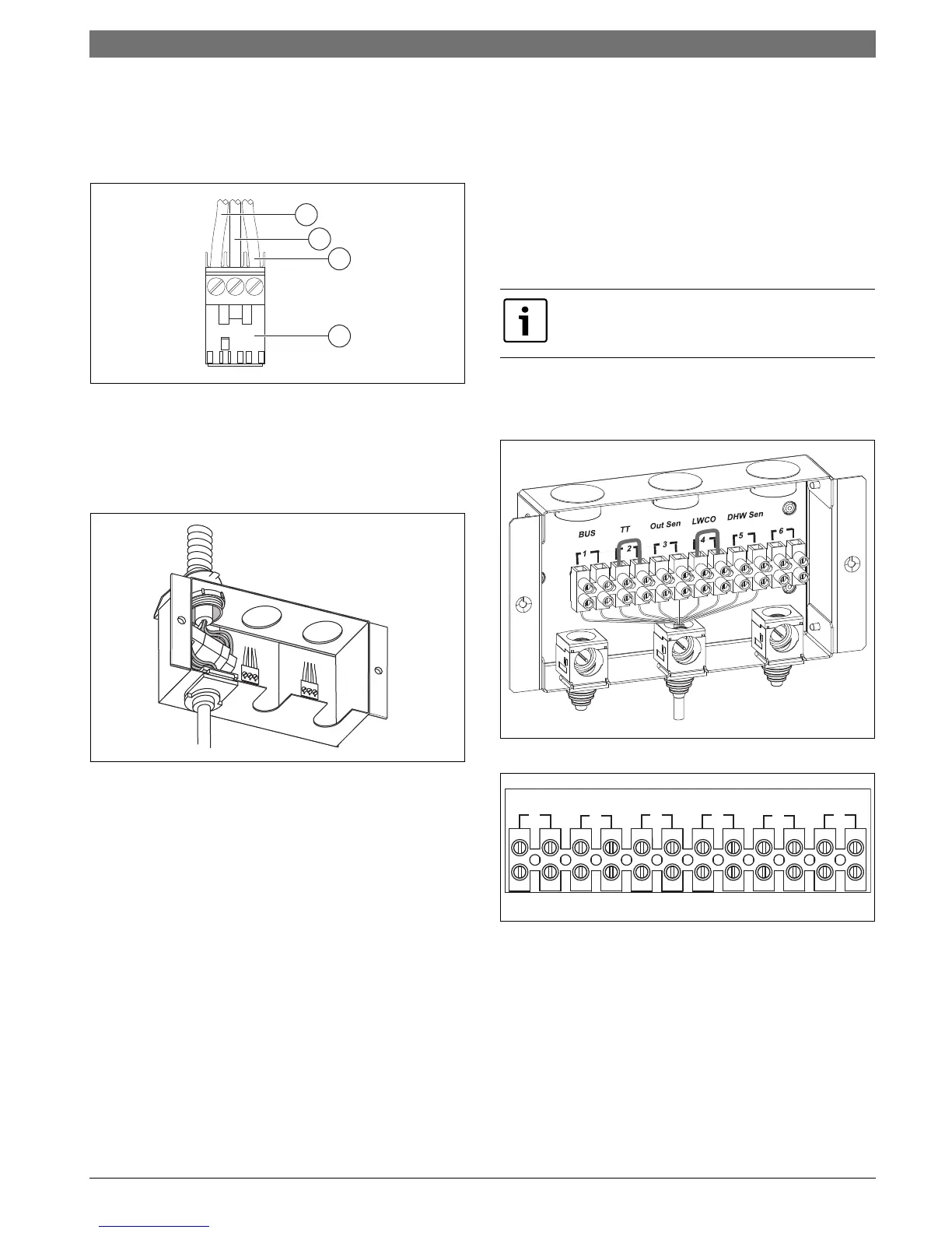
Fig. 50 Low voltage (LV) connections
Fig. 51 Low voltage (LV) terminals (pre-wire links not shown for
simplicity)
[1] BUS - BUS connection to programmer
[2] TT - Thermostat/On demand signal (pre-wired link) (dry contact)
[3] Out Sen - Outdoor temperature sensor (included with FW200
accessory)
[4] LWCO - Low Water Cut Off switch (pre-wired link) (external 24V
power required)
[5] DHW Sen - Domestic Hot Water tank temperature sensor
[6] Empty (future connectivity)
 Loading...